Rockwell Automation Publication 2198-UM002L-EN-P - October 2021 133
Chapter 5 Connect the Kinetix 5700 Drive System
Wiring Requirements Wires must be copper with 75 °C (167 °F) minimum rating. Phasing of main AC
power is arbitrary and earth ground connection is required for safe and proper
operation.
Refer to Power Wiring Examples
on page 321 for interconnect diagrams.
IMPORTANT
The National Electrical Code and local electrical codes take
precedence over the values and methods provided.
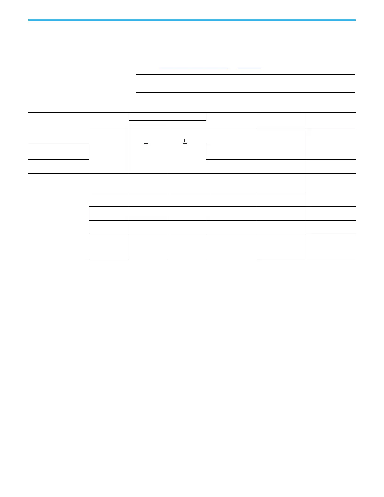
Table 70 - DC-bus Power Supply Wiring Requirements
DC-bus Power Supply
Cat. No.
Description
Connects to Terminals
Wire Size
mm
2
(AWG)
Strip Length
mm (in.)
Torque Value
N•m (lb•in)
Pin Signal
2198-P031
Mains input power
6…10
(1)
(10…8)
10.0 (0.39)
0.5…0.8
(4.4…7.1)
2198-P070
6…10
(2)
(10…8)
2198-P141
2198-P208
10…35
(8…2)
20.0 (0.79)
2.5…4.5
(22…40)
2198-Pxxx
PELV/SELV
24V power
(connector plug)
CP-1
CP-2
24V+
24V–
0.5…4
(20…12)
7.0 (0.28)
0.22…0.25
(1.9…2.2)
DC Bus power Bus bar
DC–
DC+
N/A
(3)
N/A
(3)
N/A
(3)
Contactor enable
EN–
EN+
CONT EN–
CONT EN+
0.14…2.5
(26…12)
7.0 (0.28)
0.4…0.5
(3.5…4.4)
Shunt resistor
RC-1
RC-2
SH
DC+
1.5…6
(16…10)
12.0 (0.47)
0.5…0.6
(4.5…5.3
Digital inputs
IOD-1
IOD-2
IOD-3
IOD-4
IN1
COM
IN2
SHLD
0.14…1.5
(26…16)
10.0 (0.39)
N/A
(4)
(1) Applies to solid wire. If using stranded wire, the maximum wire size is 6 mm
2
(10 AWG).
(2) Applies to solid wire. If using stranded wire, the maximum wire size is 6 mm
2
(10 AWG). To meet CE requirements above 45 °C (113 °F) for 6 mm
2
stranded wires, single-core copper
conductors must be used with 90 °C minimum rating.
(3) Shared DC-bus power connections are always made from one drive module to another over the bus-bar connection system. These terminals do not receive discrete wires.
(4) This connector uses spring tension to hold wires in place.

 Loading...


