Rockwell Automation Publication 2198-UM002L-EN-P - October 2021 171
Chapter 5 Connect the Kinetix 5700 Drive System
Motor brake conductors are customer supplied. We recommend unshielded
cable up to 90 m (295 ft).
Accessory Module
Connections
Follow these guidelines when wiring the 2198-CAPMOD-2240 capacitor
module, 2198-CAPMOD-DCBUS-IO extension module, and
2198-DCBUSCOND-RP312 DC-bus conditioner module:
• Wire module status (MS) output connections to digital input Bus
Capacitor OK, Bus Conditioner OK, or the Logix 5000™ controller
(optional).
• Flexible bus-bars (included with 2198-CAPMOD-DCBUS-IO extension
modules) are required whenever two accessory modules are mounted
side-by-side in 208 A systems. If your system does not include the
extension module, order the 2198-KITCON-DCBUSCOND or 2198-
KITCON-CAPMOD2240 replacement kit.
• Refer to DC-bus Power Supply with Capacitor Module
wiring example on
page 323.
• Refer to Regenerative Bus Supply with DC-bus Conditioner Module
wiring example on page 327
.
• Refer to Kinetix 5700 Accessory Module Status Indicators
on page 261 for
troubleshooting the module status indicators and relay output.
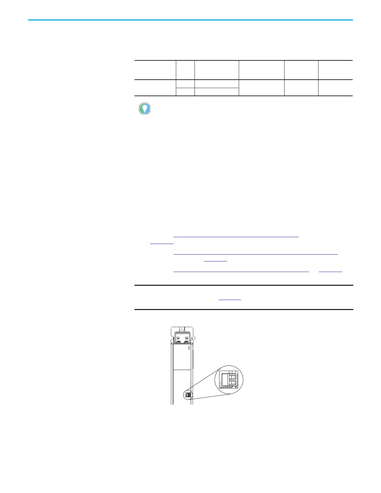
Figure 114 - MS Connector Wiring (capacitor module and DC-bus conditioner module)
Table 102 - Motor Brake (BC) Connector Specifications
Drive Module Cat.
No.
Pin Signal
Recommended Wire
Size
(AWG)
Strip Length
mm (in.)
Torque Value
N•m (lb•in)
2198-S263-ERSx
2198-S312-ERSx
BC-1 MBRK+
16 7.0 (0.28)
0.22…0.25
(1.9…2.2)
BC-2 MBRK-
Motors used with 2198-S263-ERSx and 2198-S312-ERSx inverters typically
use a brake coil that is not 24V DC. In this case, use a customer-supplied
auxiliary relay to power the customer-supplied brake coil.
IMPORTANT
To improve system performance, run wires and cables in the wireways
as established in Chapter 2. Connections to the DC bus must be made
with the shared-bus connection system.
Module Status
(MS) Connector Plug
2198-CAPMOD-2240 Capacitor Module or
2198-DCBUSCOND-RP312 DC-bus Conditioner Module

 Loading...


