78 Rockwell Automation Publication 2198-UM002L-EN-P - October 2021
Chapter 3 Mount the Kinetix 5700 Drive System
Determine Mounting Order Mount the DC-bus power supply or regenerative bus supply on the far right or
far left, whichever makes the best use of panel space. Mount inverter modules
and iTRAK® power supplies in order from left to right (as shown in Figure 43
)
or right to left (as shown in Figure 45
).
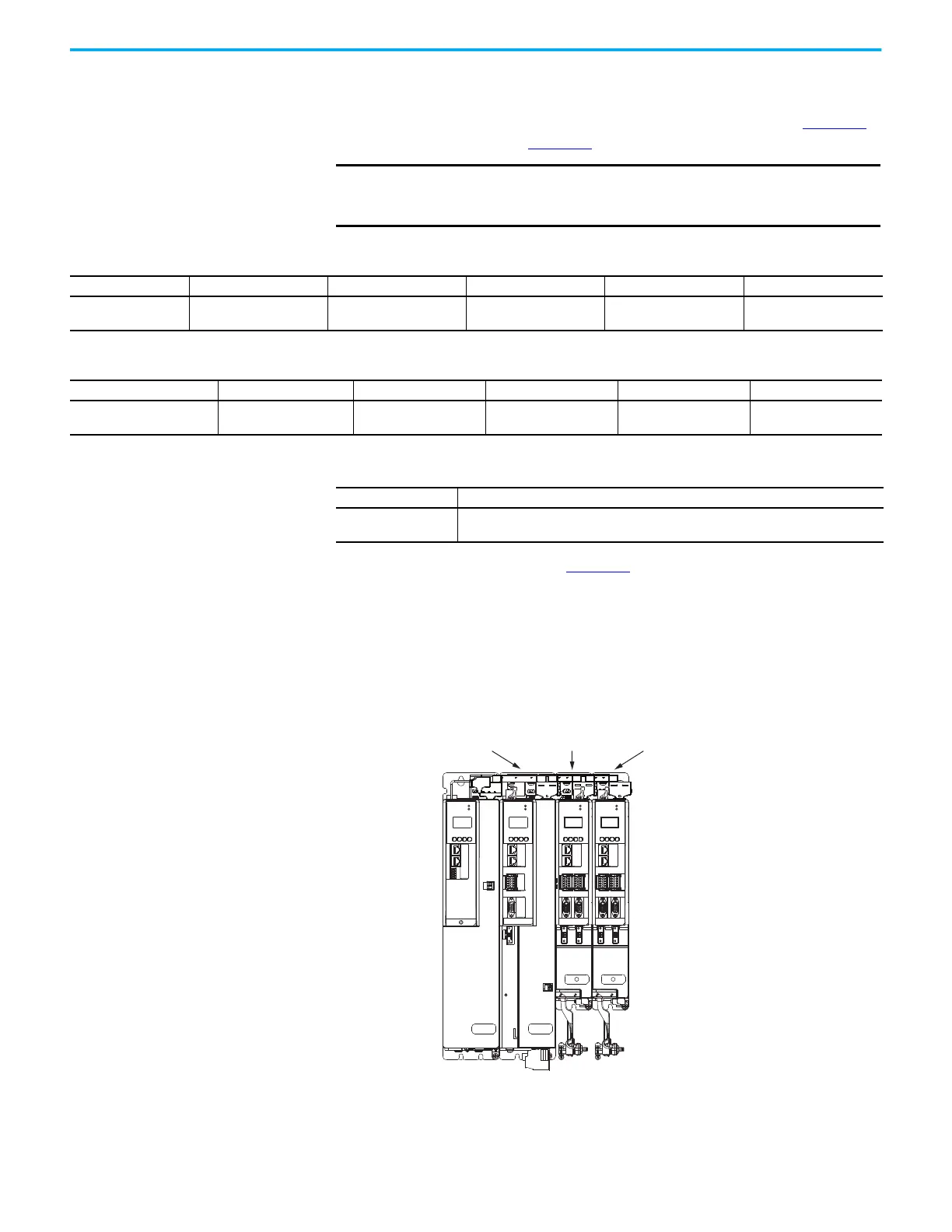
The Kinetix 5700 drive system in Figure 43
could be powered by the
2198-Pxxx DC-bus power supply or 2198-RPxxx regenerative bus supply. This
example is powered by the DC-bus power supply (positioned on the left) with
inverter modules mounted according to power rating (highest to lowest) from
left to right.
Figure 43 - System Mounting Order Example (single DC-bus power supply)
IMPORTANT
We recommend that you mount inverter modules and iTRAK power
supplies according to power rating (highest to lowest) from left to right
(or right to left) starting with the highest power rating.
Table 28 - Kinetix 5700 Single-axis Inverter Modules
Attribute 2198-S086-ERSx 2198-S130-ERSx 2198-S160-ERSx 2198-S263-ERSx 2198-S312-ERSx
Continuous Power
Output, nom
29.7 kW 44.9 kW 60.1 kW 90 kW 112 kW
Table 29 - Kinetix 5700 Dual-axis Inverter Modules
Attribute 2198-D006-ERSx 2198-D012-ERSx 2198-D020-ERSx 2198-D032-ERSx 2198-D057-ERSx
Continuous Power Output,
nom
2 x 1.7 kW 2 x 3.4 kW 2 x 5.5 kW 2 x 8.9 kW 2 x 15.9 kW
Table 30 - iTRAK Power Supply
Attribute 2198T-W25K-ER
Continuous Power
Output, nom
4.1 kW
MOD
NET
MOD
NET
MOD
NET
MOD
NET
2
1
1
4
I/O
2
1
2
1
2
1
UFB
UFB-A UFB-B
UFB-A UFB-B
D+
D-
D+
D-
D+
D-
MF-A MF-B MF-A MF-B
D+
D-
MBRK
+
-
1
I/O
6
5
10
1
I/O-A
6
510
1
I/O-B
6
510
1
I/O-A
6
510
1
I/O-B
6
510
Highest Power Utilization
Lowest Power Utilization
2198-S086-ERSx
Single-axis Inverter
2198-D012-ERSx
Dual-axis Inverter
2198-D006-ERSx
Dual-axis Inverter
2198-P141
DC-bus Power Supply
Shared-bus Connection Systems
(DC-bus and 24V DC)

 Loading...


