114 Rockwell Automation Publication 2198-UM002L-EN-P - October 2021
Chapter 4 Connector Data and Feature Descriptions
Auxiliary Feedback Specifications
The Kinetix 5700 inverters support multiple types of feedback devices by using
the 15-pin (UFB) connector and sharing connector pins in many cases. Refer to
Configure Feedback-only Axis Properties
on page 222 to use these in your
application.
Specifications for the auxiliary feedback channel are identical to the motor
feedback channel, except for specifications related to commutation and BLOB
programming.
The 9.0V and 5.0V power supplies for auxiliary feedback devices are shared
with the motor feedback channel, and the total current capability is outlined in
the table on page 111
.
Allen-Bradley Bulletin 842HR, 844D, 847H, and 847T encoders are the preferred
encoders for auxiliary feedback connections.
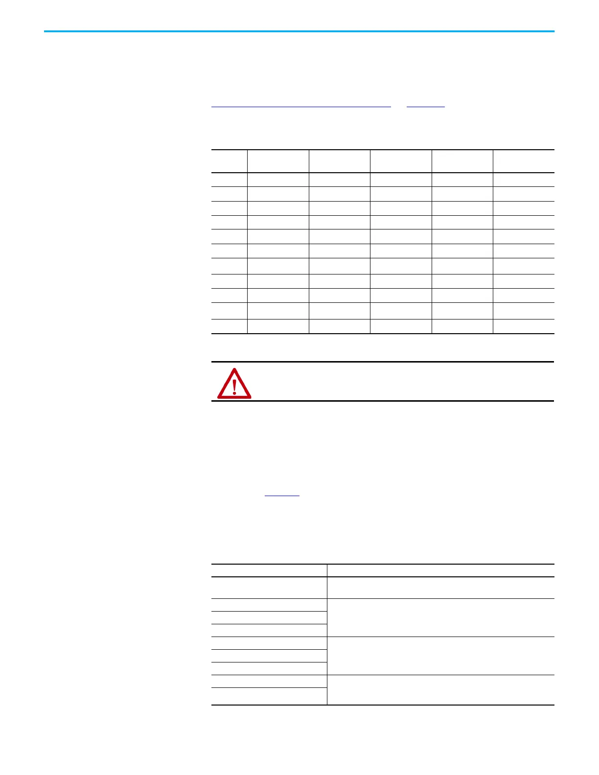
Table 60 - Auxiliary Feedback Signals by Device Type
UFB Pin Hiperface
Generic TTL
Incremental
Generic SIN/COS
Incremental
EnDat SIN/COS EnDat Digital
1 AUX_SIN+ AUX_AM+ AUX_SIN+ ENDAT_B+ –
2 AUX_SIN- AUX_AM- AUX_SIN- ENDAT_B– –
3 AUX_COS+ AUX_BM+ AUX_COS+ ENDAT_A+ –
4 AUX_COS- AUX_BM- AUX_COS- ENDAT_A– –
5 AUX_DATA+ AUX_IM+ AUX_IM+ AUX_DATA+ AUX_DATA+
6 AUX_ECOM AUX_ECOM AUX_ECOM AUX_ECOM AUX_ECOM
7
AUX_EPWR9V
(1)
––
AUX_EPWR9V
(1)
AUX_EPWR9V
(1)
9 – – – AUX_CLK+ AUX_CLK+
10 AUX_DATA- AUX_IM- AUX_IM- AUX_DATA- AUX_DATA-
14
AUX_EPWR5V
(1)
(1) Determine which power supply your encoder requires and connect to only the specified supply. Do not make connections to
both supplies.
AUX_EPWR5V AUX_EPWR5V
AUX_EPWR5V
(1)
AUX_EPWR5V
(1)
15 – – – AUX_CLK- AUX_CLK-
ATTENTION: To avoid damage to components, determine which power
supply your encoder requires and connect to either the 5V or 9V supply, but
not both.
Table 61 - Allen-Bradley Auxiliary Feedback Encoders
Cat. No. Description
842HR-MJDZ115FWYD (multi-turn)
842HR-SJDZ115FWYD (single-turn)
Size 25, sine/cosine (serial), square flange, 3/8 in. solid shaft with flat,
5…12V DC, digital RS-485 interface, M23, 17-pin connector
844D-B5CC1FW
HS35, hollow-shaft incremental encoders, rear (through-shaft),
5/8 inch, tether, 3/8 in. bolt on a 2.5…4.0 in. diameter, 5V DC in,
5V DC DLD out, MS connector, 10-pin
844D-B5CC1CS
844D-B5CC1DR
847H-DN1A-RH01024
Size 25, incremental encoder, standard square flange, 3/8 inch diameter
shaft with flat, 4.5…5.5V line driver, TTL (B-Leads-A, CW, Z gated with BN),
MS connector, 10-pin
847H-DN1A-RH02048
847H-DN1A-RH05000
847T-DN1A-RH01024 Size 20, incremental encoder, standard square flange, 3/8 inch diameter
shaft with flat, 4.5…5.5V line driver, TTL (B-Leads-A, CW, Z gated with BN),
MS connector, 10-pin
847T-DN1A-RH02048

 Loading...


