Rockwell Automation Publication 2198-UM002L-EN-P - October 2021 175
Chapter 5 Connect the Kinetix 5700 Drive System
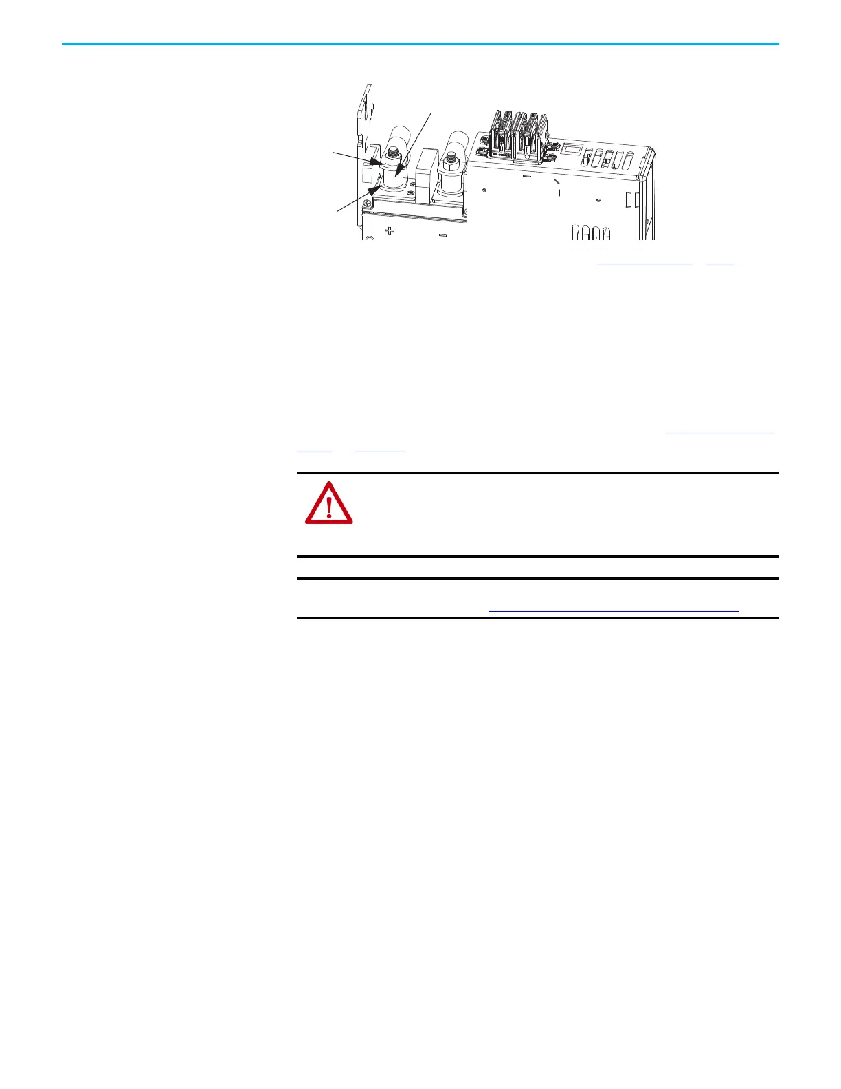
Figure 117 - Active Shunt Connections
(1) An external active shunt can be wired to any of the accessory modules. See Mount Accessory Modules on page 81 for more
information on mounting and accessory module example configurations. The 2198-CAPMOD-2240 capacitor module is
preferred because it provides additional system capacitance.
(2) Position flexible bus-bars (when two accessory modules are used) below the DC-bus lug connections. The flexible bus-bars
are used to parallel the extended DC-bus with another accessory module in 208 A systems (not required when only one
accessory module is used in 104 A systems). Flexible bus-bars are included with 2198-CAPMOD-DCBUS-IO extension modules
or you can order 2198-KITCON-CAPMOD2240 or 2198-KITCON-DCBUSCOND replacement kits.
Kinetix VPC Motors and the Extended Speed Feature
The extended speed feature is implemented in the Logix Designer application
to prevent accidental motor operation at unsafe speeds. See Field Weakening
Mode on page 439 for a description of this feature.
Powerohm Bulletin PKB and PWB active-shunt modules are required for DC-
bus system protection when Kinetix VPC motors are expected to operate in the
extended speed region at speeds exceeding the bus-overvoltage speed limit.
Considerations for Powerohm Shunt Installation
Refer to the Powerohm documentation included with your Bulletin PKB or
PWB shunt module to install, wire, and configure the module.
• To avoid nuisance thermal overload trips, configure Bulletin PKB and
PWB active-shunt modules to the highest shunt turn-on voltage setting.
The recommended setting for Line Voltage Level Jumper is JP5.
• Configure Bulletin PKB and PWB active-shunt modules in Internal
(automatic) mode. Unless an external enable signal is provided,
configure the Brake Enable Jumper in Internal (automatic) mode (JP6 is
in the downward position).
2198-DCBUSCOND-RP312
2198-CAPMOD-2240 or
2198-CAPMOD-DCBUS-IO
(1)
Accessory Modules
(2198-CAPMOD-2240 capacitor
module is shown)
Active Shunt
Lug Connections
(above spacer)
DC-bus
Lug Connections and
Flexible Bus-bars
(2)
(below spacer)
Spacer
WARNING: Kinetix VPC motor operation at speeds exceeding the bus-
overvoltage speed limit can result in personal injury and/or damage to the
drive. To avoid equipment damage and personal injury, an active shunt must be
configured in the Logix Designer application to protect the DC-bus system from
an overvoltage condition.
IMPORTANT
Refer to Motion Analyzer software to verify drive/shunt system sizing.
Access the tool at https://motionanalyzer.rockwellautomation.com.

 Loading...


