Rockwell Automation Publication 2198-UM002L-EN-P - October 2021 249
Chapter 6 Configure and Start the Kinetix 5700 Drive System
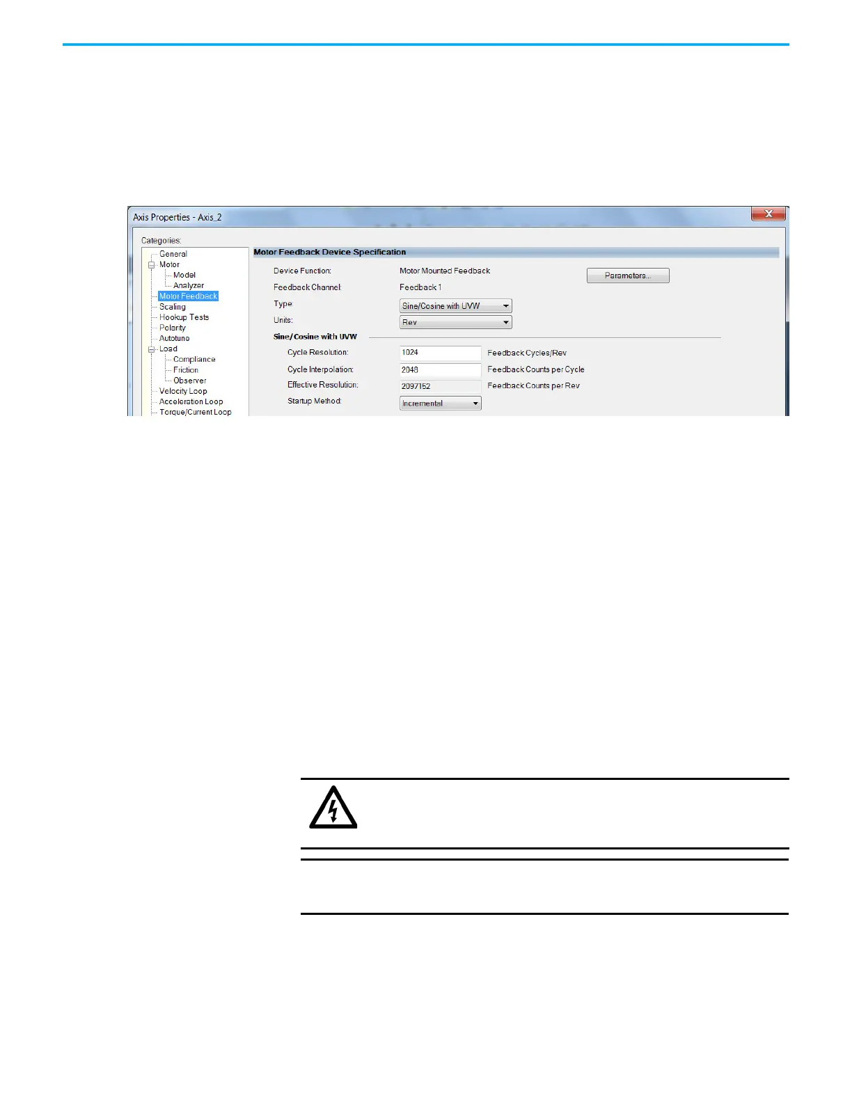
Sine/Cosine with Hall Feedback
In this example, a motor feedback device is configured for Sine/Cosine with
UVW feedback.
1. In the Controller Organizer, right-click an axis and choose Properties.
2. Select the Motor Feedback category.
The Motor Feedback Device Specification dialog box appears.
3. Configure the device function and type.
In this example, Motor Feedback is the device function and Sine/Cosine
with UVW is the feedback type.
4. Enter values for the Sine/Cosine with UVW specification fields.
The only valid values for Cycle Interpolation are powers of 2 from 4
through 65536.
5. From the Startup Method pull-down menu, choose Incremental.
6. From the Alignment pull-down menu, choose Not Aligned.
7. Click OK.
Download the Program After completing the Logix Designer application and saving the file you must
download your program to the Logix 5000 processor.
Apply Power to the
Kinetix 5700 Drive System
This procedure assumes that you have wired and configured your Kinetix 5700
system, your Logix 5000 controller, and iTRAK power supply if present.
SHOCK HAZARD: To avoid hazard of electrical shock, perform all mounting
and wiring of the Bulletin 2198 servo drives prior to applying power. Once
power is applied, connector terminals can have voltage present even when
not in use.
IMPORTANT
If multiple iTRAK power supplies are used on a track, they all need to
power up within 4 seconds of each other (or at least downstream
sections need to power up within 4 seconds of the bankmaster).

 Loading...


