Rockwell Automation Publication 2198-UM002L-EN-P - October 2021 103
Chapter 4 Connector Data and Feature Descriptions
Motor Feedback Connector Pinouts
These connector pinouts apply to the single-axis and dual-axis inverter.
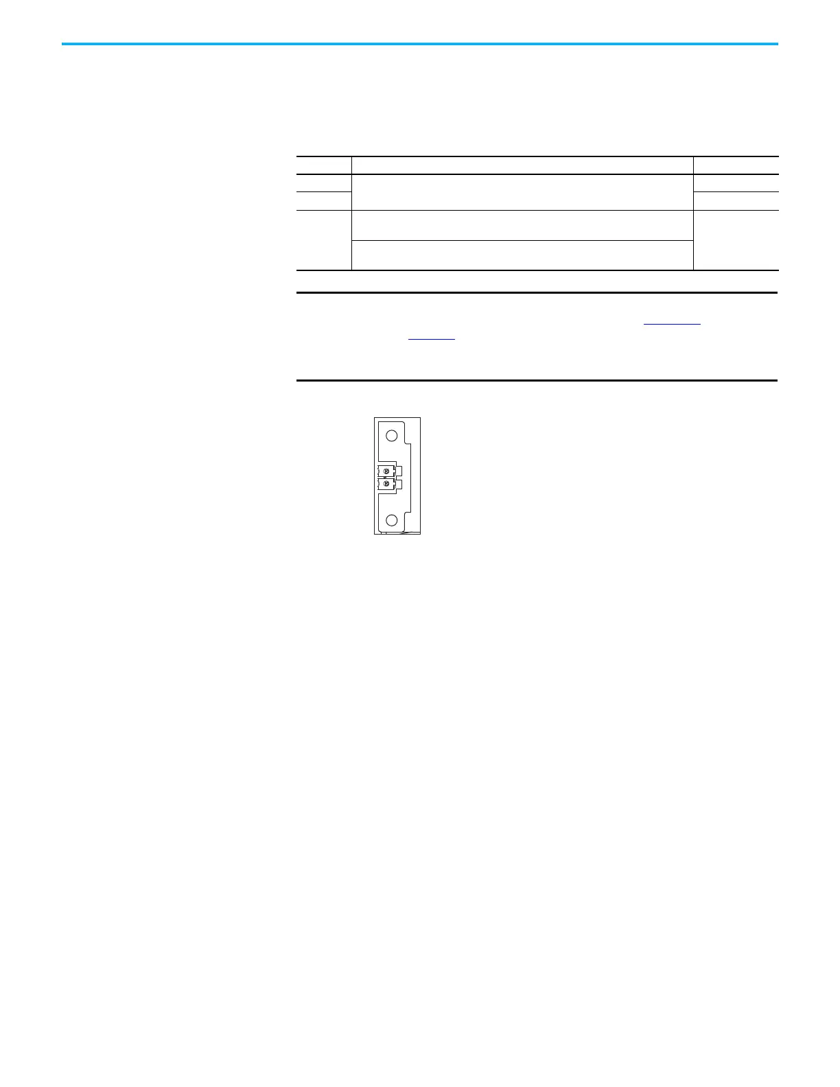
Figure 62 - Pin Orientation for 2-pin DSL Feedback (MF) Connector
Table 43 - DSL Feedback Connector
MF Pin Description Signal
1
Bidirectional data and power for digital encoder interface
D+
2D–
SHIELD
Cable shield and grounding plate (internal to 2198-KITCON-DSL connector kit)
termination point.
SHIELD
Cable shield and shield clamp (internal to 2198-H2DCK converter kit) termination
point
IMPORTANT
Drive-to-motor power cables must not exceed 90 m (295 ft), depending
on feedback type and overall system design. See Appendix D, beginning
on page 383, for more information.
System performance was tested at these cable length specifications.
These limitations also apply when meeting CE requirements.
Pin 1
Pin 2

 Loading...


