Rockwell Automation Publication 2198-UM002L-EN-P - October 2021 99
Chapter 4 Connector Data and Feature Descriptions
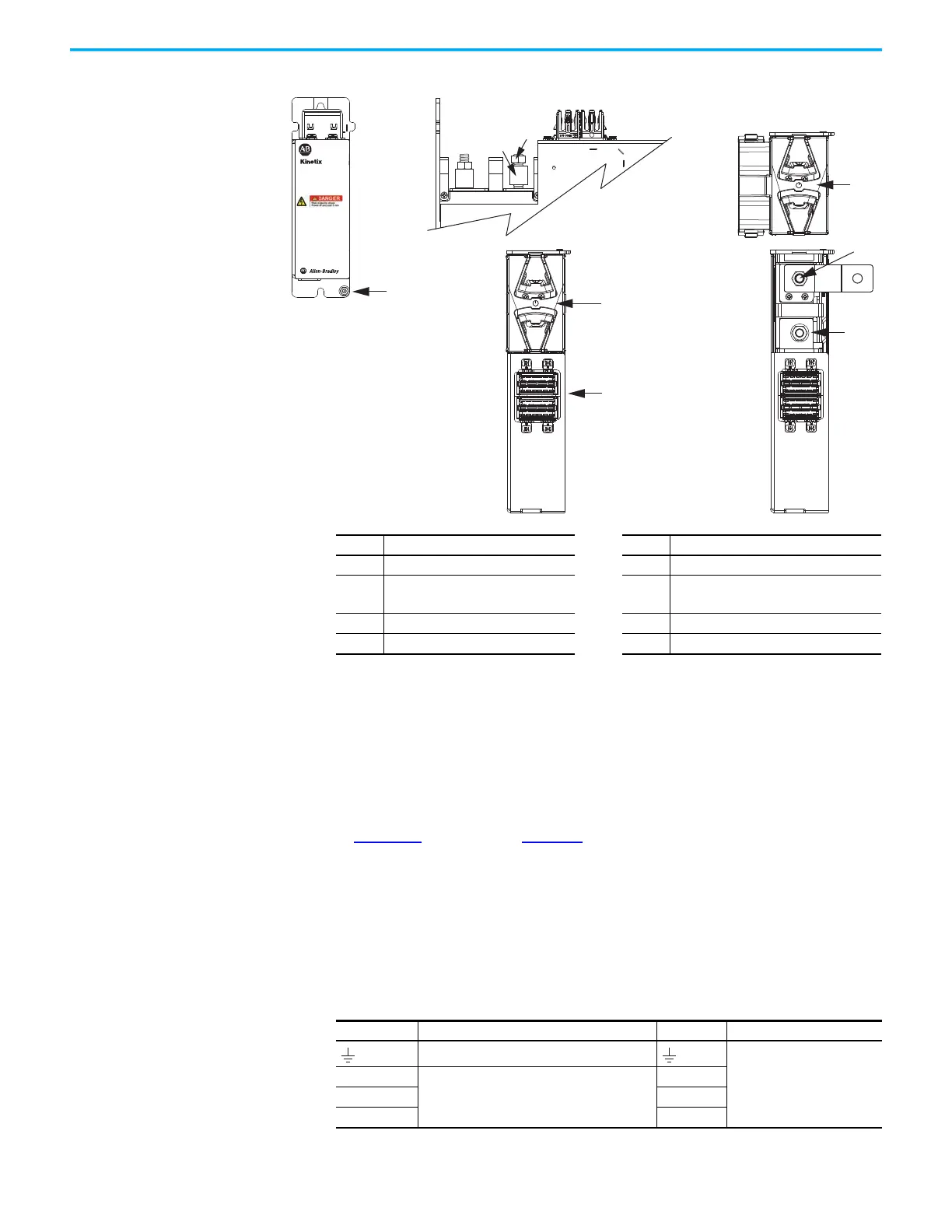
Figure 61 - Extension Module Features and Indicators
Safe Torque-off Connector Pinout
The hardwired safe torque-off (STO) connector pinouts apply to single-axis
and dual-axis inverters. For feature descriptions and wiring information, refer
to Chapter 9
beginning on page 283.
Input Power Connector Pinouts
Input power connectors include the AC input power (IPD) connector,
contactor enable (CED) connector, and the 24V input power (CP) connector.
2198-CAPMOD-DCBUS-IO
Extension Module
(side view, lug cover removed)
2198-CAPMOD-DCBUS-IO
Extension Module
(front view)
2198-CAPMOD-DCBUS-IO
Extension Module
(top views)
Item Description Item Description
1 Ground lug 5 DC– M8 stud (external DC-bus)
2
Stud/lug cover with wires
(1)
6
DC+ M8 stud (external DC-bus), shown with
flexible bus-bar
(2)
3 Stud cover without wires 7 M8 hex nut
4 DC-bus (DC) connector 8 Lug spacer
(1) This example shows the lug cover oriented for wires exiting to the left (module is on the far left of drive configuration).
Rotate lug cover 180° when wires exit to the right (module is on the far right of drive configuration).
(2) Flexible bus-bars are included with only the 2198-CAPMOD-DCBUS-IO extension module.
Table 31 - AC Input Power Connector
IPD Pin Description Signal Module
Chassis ground
• DC-bus power supply
• Regenerative bus supply
L3
Three-phase input power
L3
L2 L2
L1 L1

 Loading...


