172 Rockwell Automation Publication 2198-UM002L-EN-P - October 2021
Chapter 5 Connect the Kinetix 5700 Drive System
External Passive-shunt
Connections
Passive shunts attach to only 2198-Pxxx DC-bus power supplies. See Passive
Shunt Considerations on page 49 for shunts compatible with your DC-bus
power supply.
Follow these guidelines when wiring your 2198-Rxxx passive shunt:
• Refer to External Passive Shunt Modules
on page 70 for noise zone
considerations.
• Refer to Passive Shunt Wiring Examples
on page 337.
• Refer to the installation instructions provided with your Bulletin 2198
shunt module, publication 2198-IN011
.
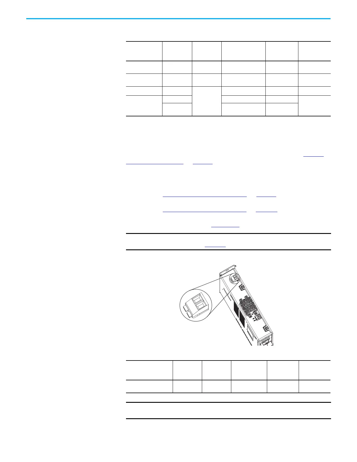
Figure 115 - RC Connector Wiring
Table 103 - Accessory Module Connector Specifications
Connector
Description
Pin Signal
Recommended Wire
Size
mm
2
(AWG)
Strip Length
mm (in.)
Torque Value
N•m (lb•in)
Module Status
MS-1
MS-2
MS
MS
0.14…1.5
(28…16)
7.0 (0.28)
0.22…0.25
(1.9…2.2)
PELV/SELV
24V power (plug)
CP-1
CP-2
24V+
24V-
0.5…4
(20…12)
7.0 (0.28)
0.22…0.25
(1.9…2.2)
DC-bus power Bus-bar
DC-
DC+
N/A
(1)
N/A
(1)
(1) DC bus connections are always made from one drive module to another over the shared-bus connection system. These
terminals do not receive discrete wires.
N/A
(1)
DC-bus studs
Bus-bar N/A N/A
18 (156)
Lugs
53.5 (1/0 AWG) 104 A
152 (300 kcmil) 208 A
N/A
(2)
(2) Strip length for the DC-bus studs depend on the customer-supplied lugs.
IMPORTANT
To improve system performance, run wires and cables in the wireways
as established in Chapter 2.
2198-Pxxx
DC-bus Power Supply
Top View
Shunt Resistor (RC) Connector Plug
Table 104 - Shunt Resistor (RC) Connector Specifications
DC-bus Power Supply
Cat. No.
Pin Signal
Recommended
Wire Size
mm
2
(AWG)
Strip Length
mm (in.)
Torque Value
N•m (lb•in)
2198-Pxxx
RC-1
RC-2
SH
DC+
1.5…6
(16…10)
12.0 (0.47)
0.5…0.6
(4.4…5.3)
IMPORTANT
You must disconnect the internal shunt wires at the RC connector before
connecting the Bulletin 2198 passive shunt resistor wires.

 Loading...


