378 Rockwell Automation Publication 2198-UM002L-EN-P - October 2021
Appendix C Size Multi-axis Shared-bus Configurations
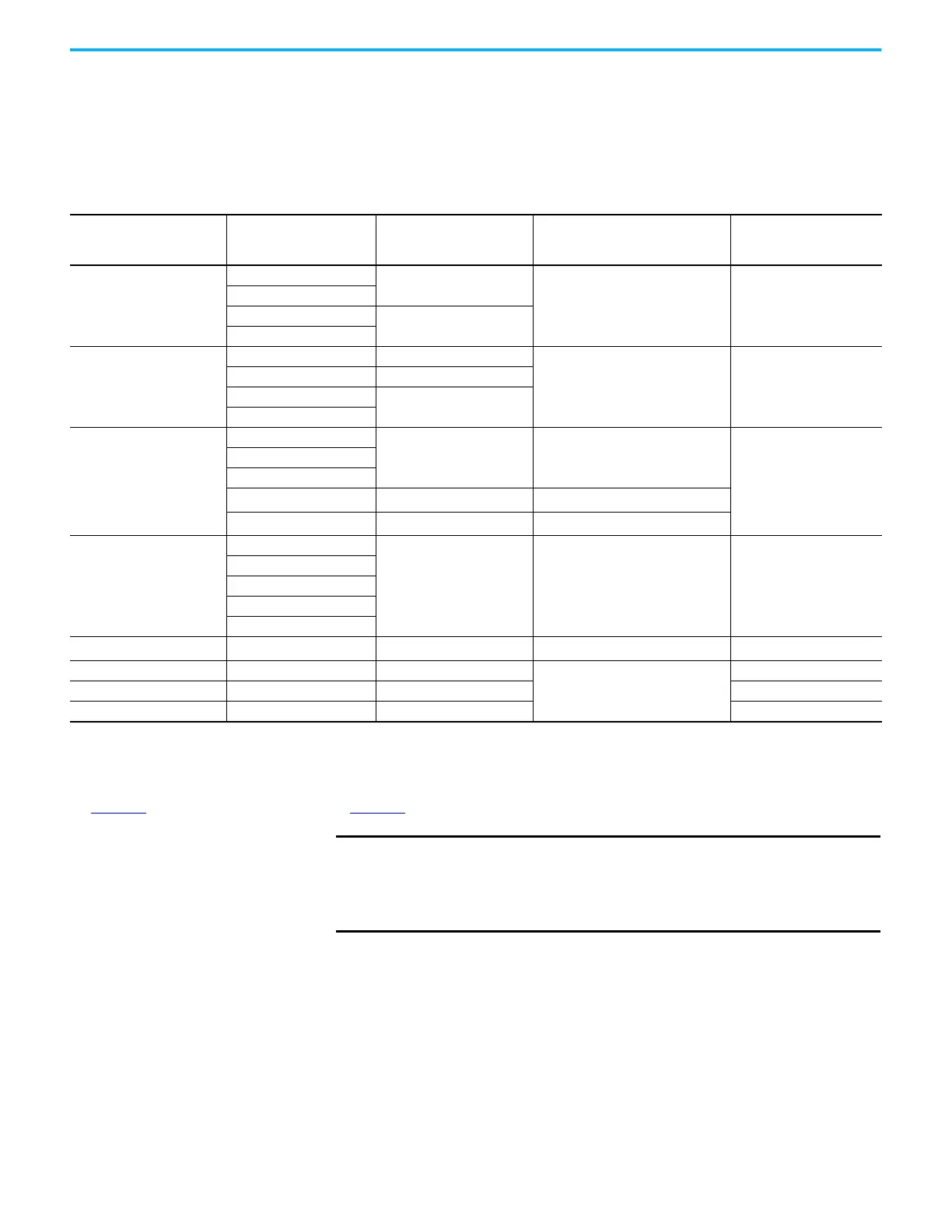
Calculate 24V DC Control Power Current Demand
If using the 24V DC shared-bus connection system to distribute control input
power to a drive cluster, output current from the 24V power supply must not
exceed 40 A.
Table 184 - Control Power Current Specifications
Drive Module
Drive Module
Cat. No.
24V Current Per Module
(non-brake motor)
A
DC
24V Current, max
(with maximum brake current)
A
DC
24V Inrush Current
(1)
A
DC-bus Power Supplies
2198-P031
0.8
–4.0
2198-P070
2198-P141
1.9
2198-P208
Regenerative Bus Supplies
2198-RP088 4.3
–4.0
2198-RP200 5.4
2198-RP263
9.1
2198-RP312
Dual-axis Inverters
2198-D006-ERSx
1.4
(2)
5.5
(3)
4.0
2198-D012-ERSx
2198-D020-ERSx
2198-D032-ERSx
1.7
(2)
7.7
(3)
2198-D057-ERSx
2.3
(2)
8.3
(3)
Single-axis Inverters
2198-S086-ERSx
4.6
9.6
(4)
4.0
2198-S130-ERSx
2198-S160-ERSx
2198-S263-ERSx
2198-S312-ERSx
iTRAK Power Supply
(5)
2198T-W25K-ER 1.3 – 2.2
Capacitor Module 2198-CAPMOD-2240 0.1
–
7.0
Extension Module 2198-CAPMOD-DCBUS-IO – –
DC-bus Conditioner Module 2198-DCBUSCOND-RP312 0.1 7.0
(1) Inrush current duration is less than 30 ms.
(2) Values are base current per module.
(3) Values assume two brake motors, each drawing the maximum rating of 2 A, are attached to each module.
(4) Values assume the maximum rated brake current of 5 A.
(5) These values represent only the iTRAK power supply. They do not include the iTRAK motor modules that are connected to the iTRAK power supply and also draw current from this 24V control
power input. For more information regarding 24V control power requirements, see iTRAK System with TriMax Bearings User Manual, publication
2198T-UM002
, or iTRAK 5730 System User Manual, publication 2198T-UM003.
IMPORTANT
If the 24V control-power output current (based on your system
calculation) exceeds 40 A, you can insert another control-power input
wiring connector at any point in your drive cluster. However, the
input connector must always extend the 24V DC-bus from left to
right.

 Loading...


