Rockwell Automation Publication 2198-UM002L-EN-P - October 2021 381
Appendix C Size Multi-axis Shared-bus Configurations
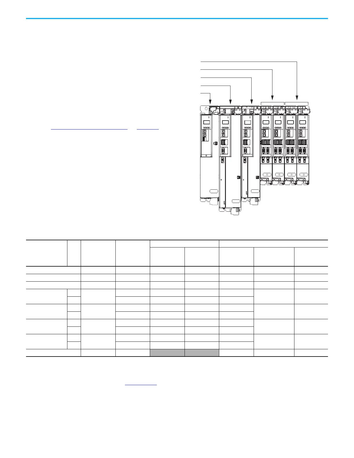
System Sizing Example This example shows how a single Kinetix 5700 drive cluster meets the total bus
capacitance, power cable length, and 24V DC current limitations.
Figure 202 - Example DC-bus Group (single drive cluster)
For more information on motor and motor-brake specifications, refer to the
Kinetix Rotary Motion Specifications Technical Data, publication
KNX-TD001
.
MOD
NET
MOD
NET
MOD
NET
MOD
NET
2
1
1
4
I/O
I/O
2
1
2
1
2
1
1
I/O-A
6
510
1
I/O-B
6
510
1
I/O-A
61
I/O-B
6
510510
UFB
UFB-A UFB-B
UFB-A UFB-B
D+
D-
D+
D-
D+
D-
MF-A MF-B MF-A MF-B
D+
D-
MBRK
+
-
16
510
D+
D-
MF
MOD
NET
2
1
I/O
UFB
D+
D-
MF
MBRK
+
-
MOD
NET
MOD
NET
2
1
2
1
1
I/O-A
6
510
1
I/O-B
6
510
1
I/O-A
61
I/O-B
6
510510
UFB-A UFB-B
UFB-A UFB-B
D+
D-
D+
D-
D+
D-
MF-A MF-B MF-A MF-B
D+
D-
16
510
2198-D006-ERSx Dual-axis Inverters
2198-D020-ERSx Dual-axis Inverters
2198-S086-ERSx Single-axis Inverter
2198-S160-ERSx Single-axis Inverter
2198-P208 DC-bus Power Supply
In this example, only 1 drive cluster defines the DC-bus group.
• Maximum motor power cable length: 1200 m (3937 ft).
See Drive to Motor Cable Lengths
on page 150 for
additional motor power cable-length limitations.
- Total motor power cable length is 337 m (1106 ft)
• Maximum supported capacitance: 13,000 μF
- Total system capacitance is 4840 μF
- External bus capacitance is 4840-2050=2790 μF
• Maximum 24V DC control power current: 40 A
- Total 24V DC control power current is 20.3 A
- The Coil Current column shows how much of the 24V
current is consumed by the motor brake circuit.
All of the total system values are within the acceptable range.
Table 185 - System Sizing Example Data
DC-bus Group
Cat. No.
Axis
Internal
Capacitance
µF
Cable Length
m (ft)
Servo Motor 24V DC Control Power Current Calculations
Servo Motor
Cat. No.
Brake Option
Yes/No
Brake Current
@ 24V DC
A
24V Current
(non-brake motor)
A
DC
Total Current
A
2198-P208 2050––––1.9 1.9
2198-S160-ERSx 1120 50 (164) MPL-B980E No – 4.6 4.6
2198-S086-ERSx 560 90 (295) MPL-B660F Yes 2.1 4.6 6.7
2198-D020-ERSx
A
390
20 (66) VPL-B1152F No –
1.4 1.4
B 15 (49) VPL-B1152F No –
2198-D020-ERSx
A
390
9 (30) VPL-B1003C Yes 0.50
1.4 2.4
B 90 (295) VPL-B1003C Yes 0.50
2198-D006-ERSx
A
165
9 (30) MPL-B310P Yes 0.50
1.4 1.9
B9 (30)MPL-B310PNo–
2198-D006-ERSx
A
165
15 (49) MPL-B310P No –
1.4 1.4
B30 (98)MPL-B310PNo–
Totals 4840 337 (1106)
3.6 16.7 20.3

 Loading...


