Rockwell Automation Publication 2198-UM002L-EN-P - October 2021 21
Chapter 1 Start
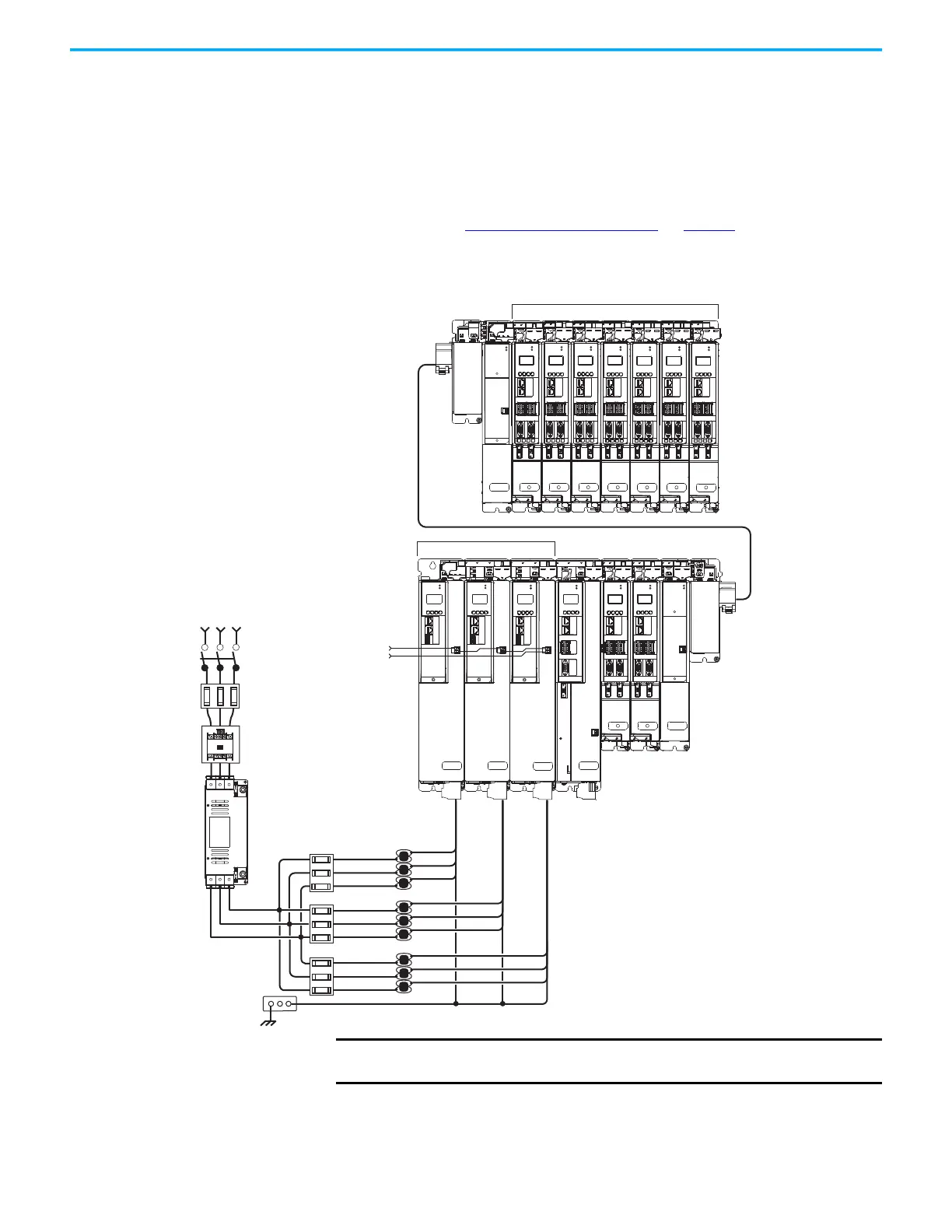
Extended DC-bus Configuration Example
In this example, two drive clusters in the same cabinet are connected by the
same 276…747V DC bus voltage. Kinetix 5700 accessory modules provide
connection points for the DC-bus at the end of cluster 1 and the beginning of
cluster 2. The Kinetix 5700 servo drive system is capable of up to 208 A DC-bus
current. Two accessory modules are needed when the DC-bus system current
exceeds 104 A. See Accessory Module Selection
on page 56 for more
information on the when accessory modules are required.
Figure 3 - Extended DC-bus Installation
MOD
NET
MOD
NET
MOD
NET
MOD
NET
2
1
1
4
I/O
2
1
2
1
2
1
UFB
UFB-A UFB-B
UFB-A UFB-B
D+
D-
D+
D-
D+
D-
MF-A MF-B MF-A MF-B
D+
D-
MBRK
+
-
MOD
NET
2
1
1
4
I/O
MOD
NET
2
1
1
4
I/O
MOD
NET
MOD
NET
2
1
2
1
UFB-A UFB-B
UFB-A UFB-B
D+
D-
D+
D-
MF-A MF-B MF-A MF-B
D+
D-
MOD
NET
2
1
UFB-A UFB-B
D+
D-
MF-A MF-B
D+
D-
MOD
NET
MOD
NET
2
1
2
1
UFB-A UFB-B
UFB-A UFB-B
D+
D-
D+
D-
D+
D-
MF-A MF-B MF-A MF-B
D+
D-
MOD
NET
2
1
UFB-A UFB-B
D+
D-
MF-A MF-B
D+
D-
MOD
NET
2
1
UFB-A UFB-B
D+
D-
MF-A MF-B
D+
D-
MODULE
STA
TUS
MOD
DC BUS
MOD
DC BUS
MODULE
STATUS
D+
D-
MF
1
I/O-A
6
510
1
I/O-B
6
510
1
I/O-A
6
510
1
I/O-B
6
510
1
I/O-A
6
510
1
I/O-B
6
510
1
I/O-A
6
510
1
I/O-B
6
510
1
I/O-A
6
510
1
I/O-B
6
510
1
I/O-A
6
510
1
I/O-B
6
510
1
I/O-A
6
510
1
I/O-B
6
510
1
I/O-A
6
510
1
I/O-B
6
510
1
I/O-A
6
510
1
I/O-B
6
510
1
I/O
6
5
10
Kinetix 5700 Servo Drives
Cluster 1 (front view)
Bonded Cabinet
Ground Bus
Kinetix 5700 Extended Servo Drives
Cluster 2 (front view)
DC-bus Extension
Shared DC-bus and
24V DC Control Power
Circuit
Protection
1321-3R80-B
Line Reactors
(required components)
2198-P208 DC-bus Power Supplies
Single-axis
Inverter
Dual-axis
Inverters
Capacitor
Module
Extension
Module
Capacitor
Module
Extension
Module
Dual-axis Inverters
Bulletin 2198 Shared-bus
Connection System
(24V shared-bus connection
system is optional)
Magnetic Contactor
(M1) Control String
Line Disconnect
Device
195…528V AC
Three-phase
Input Power
Magnetic (M1)
Contactor
2198-DBR200-F
AC Line Filter
(required for CE)
DC-bus Extension
ATTENTION: Circuit protection can be
added after the power supply cluster to
help protect converters and inverters
from damage in the event of a DC-bus
cable short-circuit.
Circuit
Protection
IMPORTANT
When two or three DC-bus power supplies are wired together in the
same drive cluster, they must all be catalog number 2198-P208.

 Loading...


