Rockwell Automation Publication 2198-UM002L-EN-P - October 2021 69
Chapter 2 Plan the Kinetix 5700 Drive System Installation
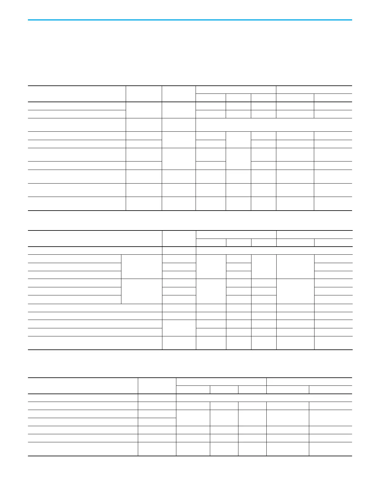
Cable Categories for Kinetix 5700 Systems
These tables indicate the best zone for running cables and wires. The tables
also show how the use of ferrite sleeves and shielded cable can reduce the noise
effects of dirty and very-dirty wires and cables.
Table 23 - DC-bus Power Supply or Regenerative Bus Supply
Wire/Cable
Power Supply
Cat. No.
Connector
Zone Method
Very Dirty Dirty Clean Ferrite Sleeve Shielded Cable
L1, L2, L3 (shielded cable)
2198-Pxxx
2198-RPxxx
IPD
–X–– X
L1, L2, L3 (unshielded cable) X – – – –
DC-/DC+ (DC bus)
2198-Pxxx
2198-RPxxx
DC Bus-bar only, no wiring connector.
DC+/SH (passive shunt) 2198-Pxxx
RC
–
X
–– –
DC+/DC– (active shunt) 2198-RPxxx ––––
CONT EN– and CONT EN+ (M1 contactor)
2198-Pxxx
2198-RPxxx
CED
–
X
–– –
CONV OK– and CONV OK+ 2198-RPxxx ––––
24V DC
2198-Pxxx
2198-RPxxx
CP – X – – –
Dedicated digital inputs
2198-Pxxx
2198-RPxxx
IOD – X – – –
Ethernet (shielded cable)
2198-Pxxx
2198-RPxxx
PORT1
PORT2
––X– X
Table 24 - Dual-axis and Single-axis Inverters
Wire/Cable
(1)
Connector
Zone Method
Very Dirty Dirty Clean Ferrite Sleeve Shielded Cable
DC-/DC+ (DC bus) DC Bus-bar only, no wiring connector.
U, V, W (motor power)
Kinetix VPL, VPC-Q
VPF, VPH, VPS
motors
MP
–
X
––
X
Motor feedback MF X X
Motor brake BC X X
U, V, W (motor power) Kinetix HPK, MMA,
VPC-S/M/Y, MPL,
MPM, MPF, MPS
motors
MP
–
X–
–
X
Motor feedback MF or UFB – X X
Motor brake BC X – X
24V DC CP – X – – –
Safety enable for safe torque-off (hardwired) STO – X – – –
Registration input
IOD
––X– X
Dedicated digital inputs (other than registration inputs) – X – – –
Ethernet (shielded cable)
PORT1
PORT2
––X– X
(1) Kinetix HPK and MMA motor power, brake, and blower cables are customer supplied.
Table 25 - iTRAK Power Supply
Wire/Cable Connector
Zone Method
Very Dirty Dirty Clean Ferrite Sleeve Shielded Cable
DC-/DC+ (DC bus) DC Bus-bar only, no wiring connector.
iTRAK DC-bus output A and B IDC – X – – X
24V DC control input power CP
–X–– X
iTRAK 24V DC control output power A and B ICP
iTRAK digital inputs IOD – – X – –
iTRAK ready output IR – – X – –
Ethernet (shielded cable)
PORT1
PORT2
––X– X

 Loading...


