88 Rockwell Automation Publication 2198-UM002L-EN-P - October 2021
Chapter 3 Mount the Kinetix 5700 Drive System
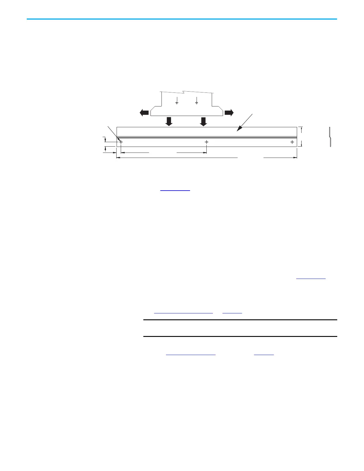
Drill-hole Patterns by Using the System Mounting Toolkit
The mounting bar must be mounted horizontally on the system panel. The
drill-hole guide inserts behind the mounting bar and slides left and right.
Holes and slots in the drill-hole guide let you establish the location of each
Kinetix 5700 drive module.
Figure 53 - Mounting Bar
For step-by-step instructions on how to use the system mounting toolkit, see
the Kinetix 5700 System Mounting Toolkit Installation Instructions,
publication 2198-IN012
.
Mount Your Kinetix 5700
Drive Modules
This procedure assumes that you have prepared your panel and understand
how to bond your system. For installation instructions regarding other
equipment and accessories, refer to the instructions that came with those
products.
A hoist, straps, and J-hooks with a lockable clasp capable of supporting the
maximum module weight are recommended for catalog numbers 2198-RP200,
2198-RP263, and 2198-RP312. For lifting instructions, see the Kinetix 5700
Regenerative Bus Supply Installation Instructions, publication 2198-IN014
.
Follow these steps to mount your Kinetix 5700 drive modules to the panel.
1. Lay out the hole pattern for each drive module in the enclosure.
See Establish Noise Zones
on page 67 for panel layout recommendations.
2. Drill holes in the panel for mounting your drive system.
Refer to Drill-hole Patterns
beginning on page 85.
2x 190 (7.48)
2x 10 (0.39)
400 (15.75)
3x Ø4.50 (0.18)
10 (0.39)
43.2 (1.70) Ref
100
100
Mounting Bar
Drill-hole Guide
Dimensions are in mm (in.)
M4 thread-forming
fasteners, 1.7 N•m (15 lb•in)
IMPORTANT
To improve the bond between the drive modules and subpanel,
construct your subpanel out of zinc plated (paint-free) steel.

 Loading...


