Rockwell Automation Publication 2198-UM002L-EN-P - October 2021 51
Chapter 2 Plan the Kinetix 5700 Drive System Installation
See External Active-shunt Connections on page 173, when making active shunt
connections.
Enclosure Selection
This example is provided to assist you in sizing an enclosure for your
Kinetix 5700 drive system. You need heat dissipation data from all components
planned for your enclosure to calculate the enclosure size (refer to Table 19
).
With no active method of heat dissipation (such as fans or air conditioning)
either of the following approximate equations can be used.
If the maximum ambient rating of the Kinetix 5700 drive system is 50 °C
(122 °F) and if the maximum environmental temperature is 20 °C (68 °F), then
T=30. In this example, the total heat dissipation is 416 W (sum of all
components in enclosure). So, in the equation below, T=30 and Q=416.
In this example, the enclosure must have an exterior surface of at least 2.99 m
2
.
If any portion of the enclosure is not able to transfer heat, do not include that
value in the calculation.
Because the minimum cabinet depth to house the Kinetix 5700 system
(selected for this example) is 300 mm (11.8 in.), the cabinet needs to be
approximately 1500 x 700 x 300 mm (59.0 x 27.6 x 11.8 in.) HxWxD.
1.5 x (0.300 x 0.70) + 1.5 x (0.300 x 2.0) + 1.5 x (0.70 x 2.0) = 3.31 m
2
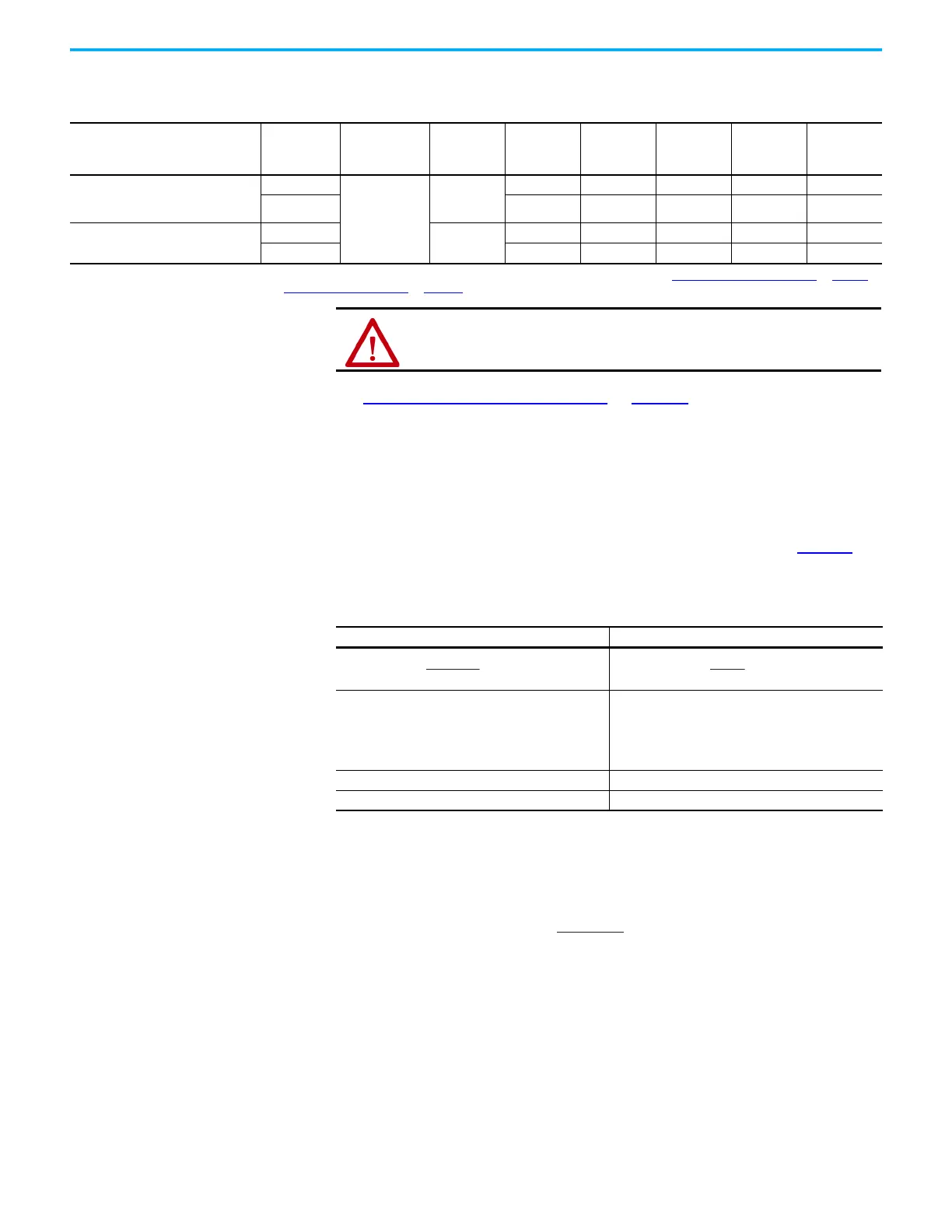
Table 18 - Compatible Active Shunt Specifications (no internal brake resistor)
Kinetix 5700 Power Supply
Powerohm
Resistors
Cat. No.
(1)
Input Voltage,
nom
Turn -on
Bus Voltage
Continuous
Power
kW
Resistance
(internal)
Ω
Resistance
(minimum)
Ω
Continuous
Current
Amps
Peak
Current
Amps
2198-Pxxx DC-bus power supply or
2198-RPxxx regenerative bus supply
when DC-bus regulation is not enabled.
PWB035
480V AC
750V DC
26.25 – 7.5 35 100
PWB110 82.5 – 2.5 110 300
2198-RPxxx regenerative bus supply
when DC-bus regulation is enabled.
PWB035-800
800V DC
26.25 – 8.0 35 100
PWB110-800 82.5 – 2.7 110 300
(1) How the Powerohm PWBxxx shunts connect to the 2198-Pxxx DC-bus power supply and 2198-RPxxx regenerative bus supply is explained in External Active-shunt Connections on page 173
and illustrated with interconnect diagrams in Active Shunt Wiring Examples
on page 338.
ATTENTION: Do not use Powerohm active-shunt modules at input line
voltages that exceed 528V AC. Active-shunt thermal-overload shutdown can
occur if input line voltage exceeds 528V AC.
Metric Standard English
Where T is temperature difference between inside air
and outside ambient (°C), Q is heat generated in
enclosure (Watts), and A is enclosure surface area (m
2
).
The exterior surface of all six sides of an enclosure is
calculated as:
Where T is temperature difference between inside air
and outside ambient (°F), Q is heat generated in
enclosure (Watts), and A is enclosure surface area (ft
2)
.
The exterior surface of all six sides of an enclosure is
calculated as:
A = 2dw + 2dh + 2wh A = (2dw + 2dh + 2wh) /144
Where d (depth), w (width), and h (height) are in meters. Where d (depth), w (width), and h (height) are in inches.
A =
0.38 (416)
1.8 (30) - 1.1
= 2.99 m
2

 Loading...


