Rockwell Automation Publication 2198-UM002L-EN-P - October 2021 143
Chapter 5 Connect the Kinetix 5700 Drive System
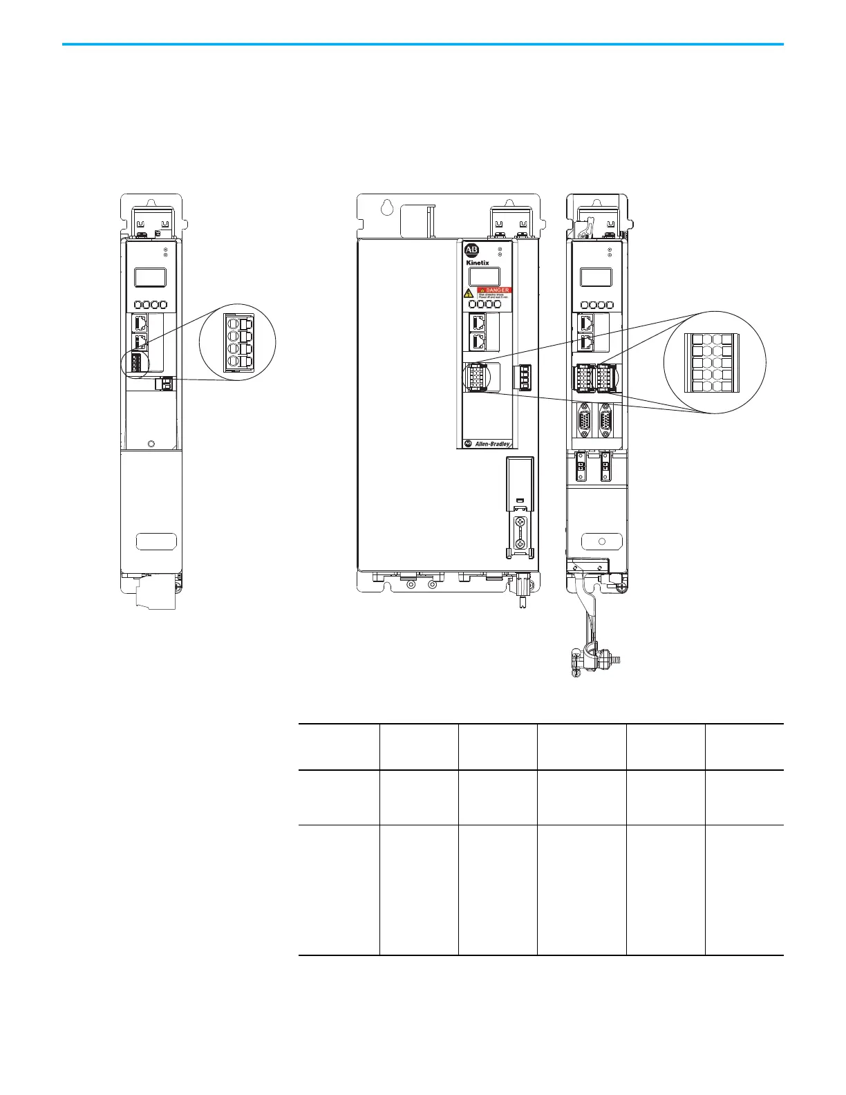
Wire the Digital Inputs Connector
The digital inputs (IOD) connector applies to the DC-bus power supply,
2198-RPxxx regenerative bus supply, single-axis inverter, and dual-axis
inverters and use spring tension to hold wires in place.
Figure 91 - IOD Connector Wiring
2198-Pxxx
DC-bus Power Supply
(front view)
1
I/O-A
6
10
1
I/O-B
6
5
10
UFB-A
UFB-B
D+
D-
D+
D-
MF-A
MF-B
MOD
NET
2
1
5
1
10
5
6
1
2
3
4
5
10
9
8
7
6
MOD
NET
2
1
1
I/O
6
5
10
OK+
OK–
EN–
EN+
5700
2198-Sxxx-ERSx
Single-axis Inverters or
2198-Dxxx-ERSx
Dual-axis Inverters Front View
(2198-xxxx-ERS4 is shown)
10-pin Digital Inputs
(IOD) Connector Plug
4-pin Digital Inputs
(IOD) Connector Plug
2198-RPxxx
Regenerative Bus Supply
(front view)
Table 79 - Digital Inputs (IOD) Connector Specifications
Drive Module
Cat. No.
IOD Pin Signal
Recommended
Wire Size
mm
2
(AWG)
Strip Length
mm (in.)
Torque Value
N•m (lb•in)
2198-Pxxx
IOD-1
IOD-2
IOD-3
IOD-4
IN1
COM
IN2
SHLD
0.14…1.5
(26…16)
10.0 (0.39)
N/A
(1)
(1) This connector uses spring tension to hold wires in place.
2198-RPxxx
2198-Dxxx-ERSx
2198-Sxxx-ERSx
IOD-1
IOD-2
IOD-3
IOD-4
IOD-5
IOD-6
IOD-7
IOD-8
IOD-9
IOD-10
IN1
COM
IN2
COM
SHLD
IN3
COM
IN4
COM
SHLD
0.14…1.5
(26…16)
10.0 (0.39)
N/A
(1)

 Loading...


