26 Rockwell Automation Publication 2198-UM002L-EN-P - October 2021
Chapter 1 Start
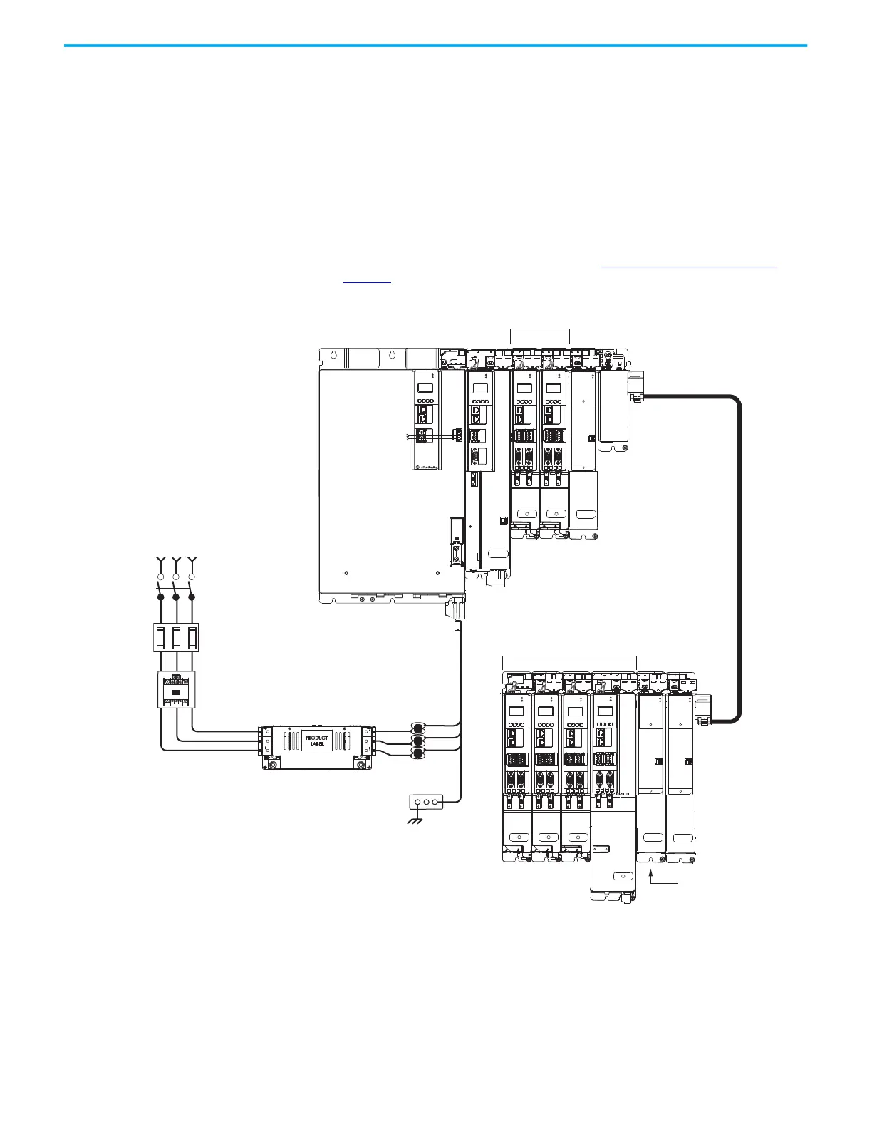
Extended Regenerative Bus Configuration Example
In this example, two drive clusters in the same cabinet are connected by the
same 458…747V DC bus voltage.
• Kinetix 5700 accessory modules provide connection points for the DC
bus at the end of cluster 1 and the beginning of cluster 2.
• The Kinetix 5700 servo drive system is capable of up to 208 A DC-bus
current. Two parallel accessory modules are needed when the DC-bus
system current exceeds 104 A.
• The DC-bus conditioner module is required when the combined motor
cable length exceeds 400 m (1312 ft). See Accessory Module Selection
on
page 56
for more information on accessory module requirements.
Figure 8 - Extended DC-bus Installation
MOD
NET
2
1
UFB-A UFB-B
D+
D-
MF-A MF-B
MOD
NET
2
1
UFB-A UFB-B
D+
D-
MF-A MF-B
D+
D-
MOD
NET
2
1
D+
D-
MF-A MF-B
D+
D-
MOD
NET
MOD
NET
MOD
NET
2
1
2
1
2
1
UFB
UFB-A UFB-B
UFB-A UFB-B
D+
D-
D+
D-
D+
D-
MF-A MF-B MF-A MF-B
D+
D-
MBRK
+
-
MOD
NET
D+
D-
MF
MODULE
STATUS
MOD
NET
MODULE
STATUS
MOD
NET
2
1
UFB-A UFB-B
D+
D-
MF-A MF-B
D+
D-
MOD
NET
MODULE
STATUS
1
I/O-A
6
510
1
I/O-B
6
510
1
I/O
6
5
10
1
I/O-A
6
510
1
I/O-B
6
510
1
I/O-A
6
510
1
I/O-B
6
510
1
I/O-A
6
510
1
I/O-B
6
510
1
I/O-A
6
510
1
I/O-B
6
510
1
I/O-A
6
510
1
I/O-B
6
510
MOD
NET
2
1
1
I/O
6
5
10
OK+
OK–
EN–
EN+
Kinetix 5700 Drive System
Cluster 1 (front view)
Kinetix 5700 Extended Drive System
Cluster 2 (front view)
DC-bus Extension
Shared DC-bus and 24V DC
Control Power
Magnetic Contactor
(M1) Control String
Dual-axis Inverters
Dual-axis Inverters
Line Disconnect
Device
324…506V AC
Three-phase Input Power
Circuit
Protection
Magnetic (M1)
Contactor
Bonded Cabinet
Ground Bus
2198-DBRxx-F
AC Line Filter
(required for CE)
Regenerative Bus Supply
2198-CAPMOD-DCBUS-IO
Extension Module
2198-CAPMOD-2240
Capacitor Module
2198-CAPMOD-2240
Capacitor Module
2198-DCBUSCOND-RP312
DC-bus Conditioner Module
Combined motor
cable lengths equal
300 m (984 ft).
Combined motor
cable lengths equal
480 m (1575 ft).
Single-axis
Inverter
ATTENTION: Circuit protection can be
added after the power supply cluster to
help protect converters and inverters
from damage in the event of a DC-bus
cable short-circuit.
Bulletin 1321
Line Reactor
(recommended)

 Loading...


