338 Rockwell Automation Publication 2198-UM002L-EN-P - October 2021
Appendix A Interconnect Diagrams
Active Shunt Wiring
Examples
Active shunts are available from the Rockwell Automation Encompass™
partner Powerohm Resistors, Inc. (http://www.powerohm.com)
.
For compatible Powerohm active shunts paired with 2198-Pxxx DC-bus power
supplies and 2198-RPxxx regenerative bus supplies, see External Active-shunt
Connections on page 173.
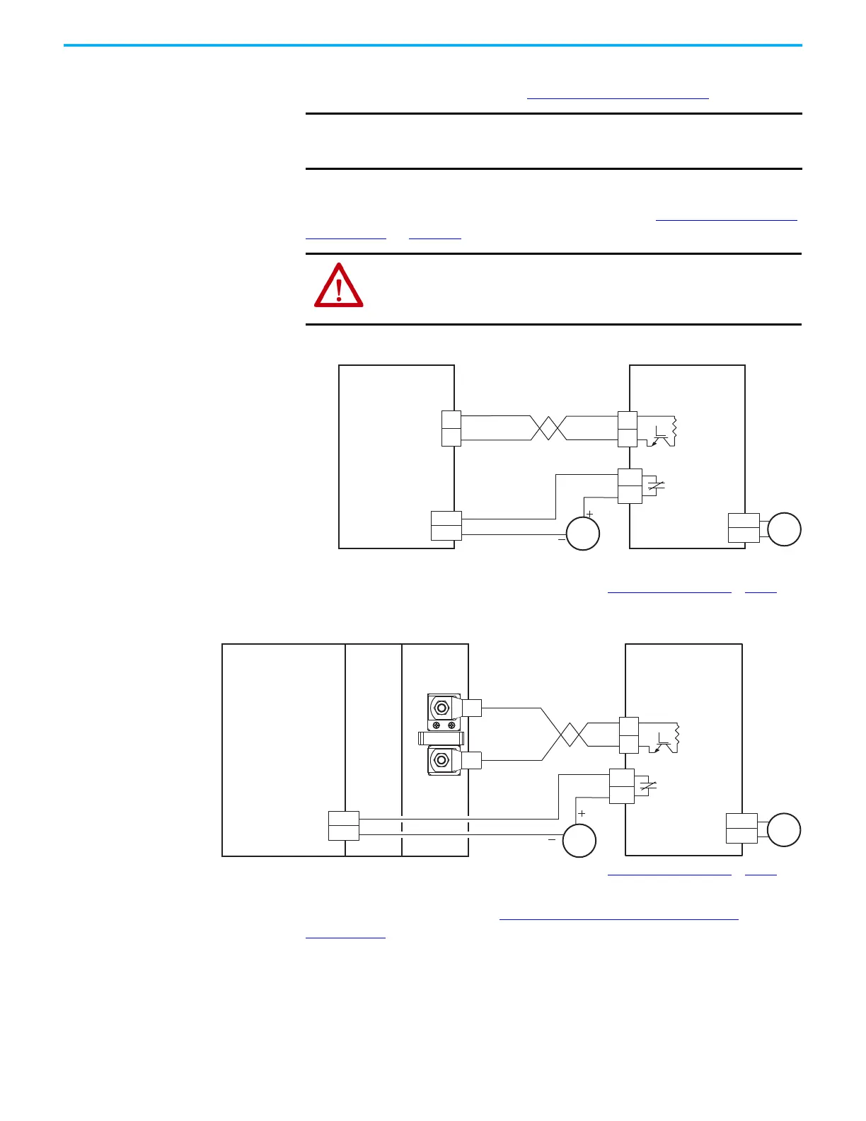
Figure 177 - 2198-RPxxx Supply with External Active Shunt (built-in brake resistor)
(1) The active shunt (RC) connector is rated for wire size up to 6 mm
2
(10 AWG). When conductors larger than 6 mm
2
(10 AWG)
connect to the shunt, the drive connection must be made to the external DC-bus connections on an accessory module.
(2) Configure any available digital input as Shunt Thermal Switch OK. See the Digital Inputs Connector Pinouts
on page 101.
(3) Powerohm PKB050 and PKB050-800 shunts require 120V AC between pins 9 and 10 to supply power to the cooling fans.
Figure 178 - 2198 Power Supply with External Active Shunt (built-in brake resistor)
(1) Configure any available digital input as Shunt Thermal Switch OK. See the Digital Inputs Connector Pinouts on page 101.
(2) Powerohm PKB050 and PKB050-800 shunts require 120V AC between pins 9 and 10 to supply power to the cooling fans.
See Knowledgebase Technote: Using PKB external active shunt with
Kinetix 5700 for more information on wiring to these Powerohm Bulletin
PKBxxx active shunts.
IMPORTANT
Powerohm Bulletin PKBxxx active shunt modules use built-in internal
brake resistors. Bulletin PWBxxx active shunt modules require
appropriately sized external brake resistors.
ATTENTION: To avoid damage to the Kinetix 5700 drive system, wire the
active shunt thermal switch to a digital input on the power supply and
configure the Shunt Thermal Switch OK function in the Logix Designer
application.
DC+
DC–
(2)
INx
COM
DC+
DC–
(1)
120V AC
9
10
3
4
(3)
24V DC
2198-RPxxx
Regenerative Bus Supply
Powerohm
Bulletin PKB-xxx-xxx
Active Shunt Module
Fault Contact
Digital Input
(IOD) Connector
Shunt (RC)
Connector
Resistor
4.6 m (15 ft) Maximum Cable Length
DC+
DC–
120V AC
9
10
3
4
DC+
DC–
INx
COM
24V DC
(1)
(2)
2198-Pxxx
DC-Bus Power Supply
or
2198-RPxxx
Regenerative Bus Supply
Powerohm
Bulletin PKBxxx-xxx
Active Shunt Module
Fault Contact
Digital Input
(IOD) Connector
External DC-bus
Resistor
4.6 m (15 ft) Maximum Cable Length
2198-xxxx-ERSx
Inverter
2198-CAPMOD-2240
Capacitor Module

 Loading...


