48 Rockwell Automation Publication 2198-UM002L-EN-P - October 2021
Chapter 2 Plan the Kinetix 5700 Drive System Installation
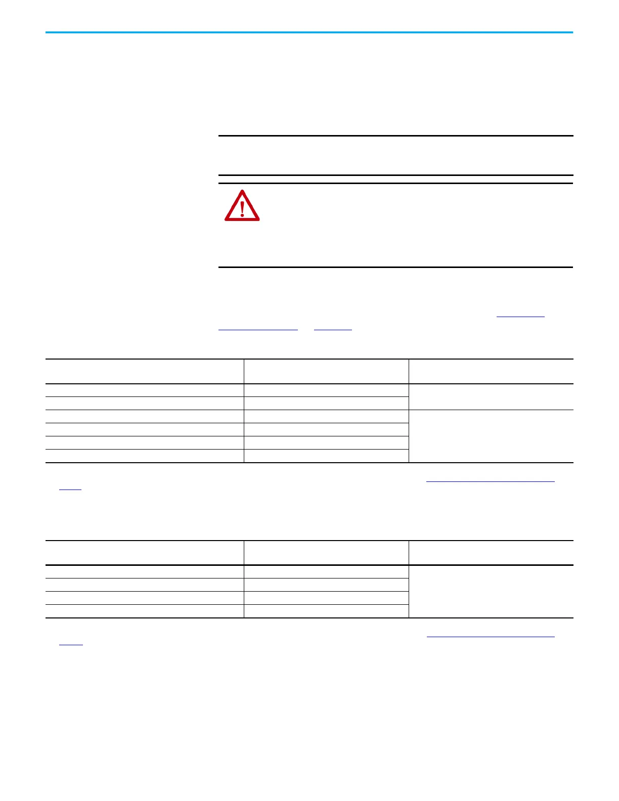
Contactor Selection
The AC three-phase contactor control string must be wired in series with the
contactor-enable relay at the CED connector. The contactor-enable relay
(applies to 2198-Pxxx DC-bus power supply and 2198-RPxxx regenerative bus
supply) is rated at 24V DC (28V, max) and 1.0 A, max.
Contactor with auxiliary contacts is strongly recommended when used with
2198-RPxxx regenerative bus supply. Wire auxiliary contact to digital input #2
(default setting) to monitor the three-phase input power. See Contactor
Wiring Examples on page 336 for wiring examples.
ATTENTION: Wiring the contactor-enable relay is required. To avoid
personal injury or damage to the system, wire the contactor-enable relay
into your control string so that:
• three-phase power is removed and the power supply is protected under
various fault conditions.
• three-phase power is never applied to the Kinetix 5700 drive system before
control power is applied.
IMPORTANT
Applying more than 28V DC control voltage or more than 1.0 A control
current to the contactor can cause permanent damage to the DC-bus
power supply or regenerative bus supply.
Table 13 - DC-bus Power Supply Contactor Specifications
DC-bus Power Supply
Cat. No.
Contactor
(1)
(2)
Cat. No.
Intermediate Relay
(3)
Cat. No.
2198-P031 100-C16EJ10
N/A
2198-P070 100-C37EJ10
2198-P141 100-C72DJ10
700-HB32Z24 (relay)
700-HN153 (socket)
2198-P208 100-C97DJ10
2198-P208 (2 in parallel) 100-E190KJ11
2198-P208 (3 in parallel) 100-E305KJ11
(1) Auxiliary contact configuration 10 indicates there is 1 N.O. and 0 N.C. contacts. Other configurations are available.
(2) For contactors that are not Bulletin 100-E type, the integrated diode is required with the contactor coil. See Knowledgebase Technote: Surge Suppressors: for Relays, Contactors and
Starters for more information.
(3) These DC-bus power supplies require an additional intermediate relay used with the contactor.
Table 14 - Regenerative Bus Supply Contactor Specifications
Regenerative Bus Supply
Cat. No.
Contactor
(1)
(2)
Cat. No.
Intermediate Relay
Cat. No.
2198-RP088 100-C43EJ10
N/A
2198-RP200 100-E116KJ11
2198-RP263 100-E205KJ11
2198-RP312 100-E265KJ11
(1) Auxiliary contact configuration 10 indicates there is 1 N.O. and 0 N.C. contacts. 11 indicates there is 1 N.O. and 1 N.C. contact. Other configurations are available.
(2) These contactor catalog numbers include a 24V DC coil. For contactors that are not Bulletin 100-E type, see Knowledgebase Technote: Surge Suppressors: for Relays, Contactors and
Starters for more information.

 Loading...


