Rockwell Automation Publication 2198-UM002L-EN-P - October 2021 261
Chapter 7 Troubleshoot the Kinetix 5700 Drive System
Kinetix 5700 Accessory Module Status Indicators
The Kinetix 5700 accessory modules include the 2198-CAPMOD-2240 capacitor
module and 2198-DCBUSCOND-RP312 DC-bus conditioner module.
Capacitor Module
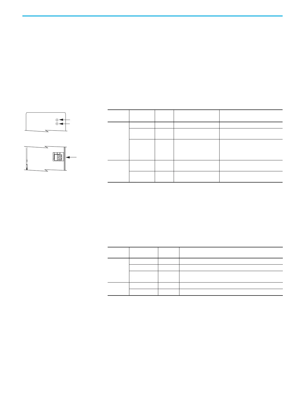
Status indicators and the module status (MS) connector are on the front of the
module. The module status connector is an output suitable for wiring to a
DC-bus power supply, regenerative bus supply, or inverter digital input
assigned as Bus Capacitor OK, or the Logix 5000 controller.
DC-bus Conditioner Module
Status indicators and the module status (MS) connector are on the front of the
module. The module status connector is an output suitable for wiring to a
DC-bus power supply, regenerative bus supply, or inverter digital input
assigned as Bus Conditioner OK, or the Logix 5000 controller.
Table 132 - Capacitor Module Status Indicators and Relay Output
Status
Indicators
Status
Relay
(1)
Output
(1) Wiring the module status relay output is optional.
Description Resolution
Module
status
Steady off Open 24V DC is not present. –
Steady green Closed
24V DC is present and
internal fuse is closed.
–
Steady red Open
24V DC is present and
internal fuse is open.
• Cycle control and bus power
• Verify that AC input meets
specifications
• Replace the module if fault persists
DC-bus
status
Steady off Open
24V DC is not present or
DC-bus measures < 50V DC.
–
Steady green Closed
24V DC is present and
DC-bus measures > 50V DC.
–
Table 133 - DC-bus Conditioner Module Status Indicators and Relay Output
Status
Indicators
Status
Relay
Output
Description
Module
status
Steady off Open 24V DC is not present
Steady green Closed 24V DC is present and internal fuse is closed
Steady red
(1)
(1) Remove DC-bus power and cycle control power. If the fault persists, the internal fuse is blown and the module needs to be
replaced. If the fault clears, then there was a thermal fault caused by a system issue. If the fault persists and the rest of the
system is functioning properly, add more DC-bus conditioners to the system to reduce thermal stress on the module.
Open
• 24V DC is present and internal fuse is open
• Over temperature event occurred
DC-bus
status
Steady off – 24V DC is not present or DC-bus measures < 50V DC
Steady green – 24V DC is present and DC-bus measures > 50V DC
Module Status Indicator
DC-bus Status Indicator
Kinetix 5700 Accessory Modules
Module Status
(MS) Connector

 Loading...


