156 Rockwell Automation Publication 2198-UM002L-EN-P - October 2021
Chapter 5 Connect the Kinetix 5700 Drive System
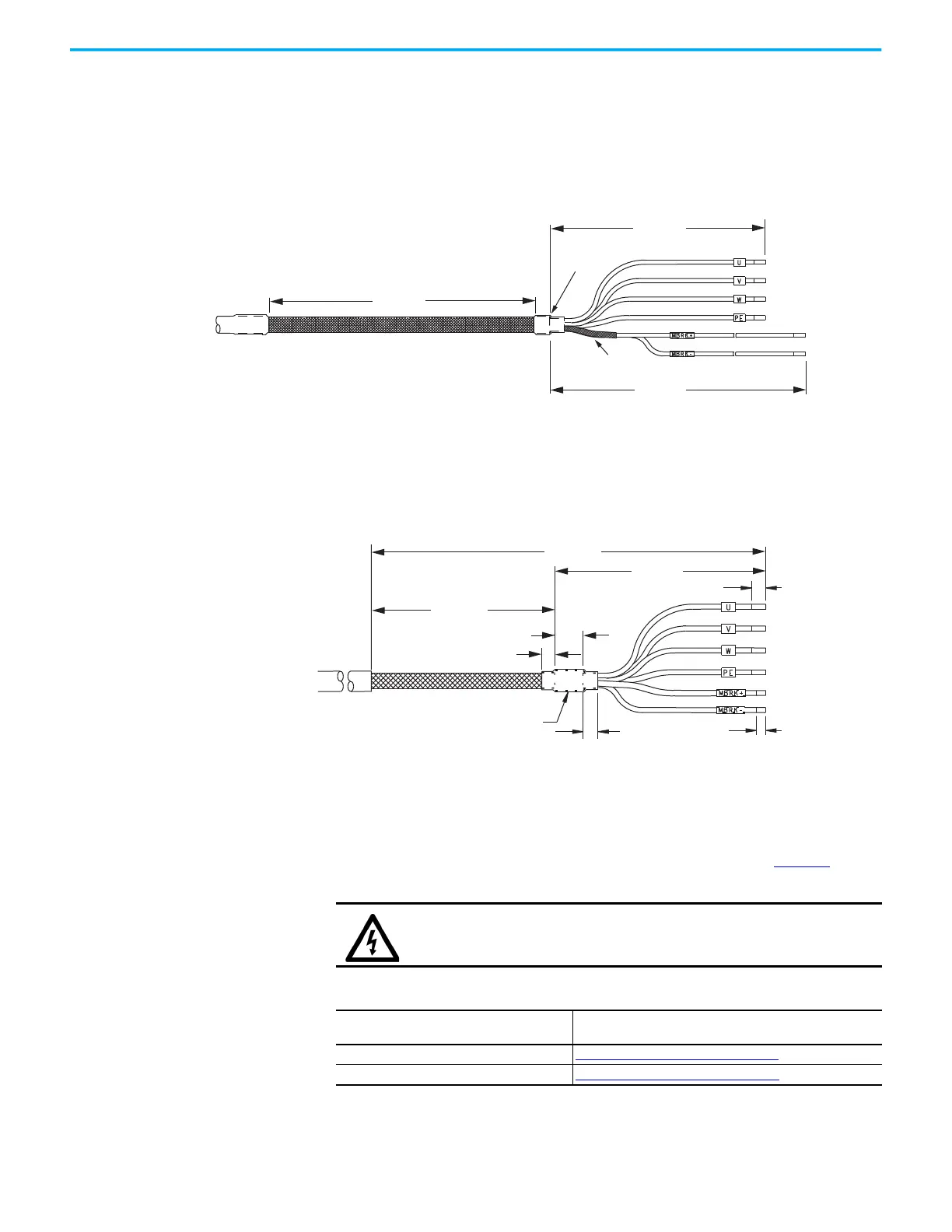
Motor Power/Brake Cable Series Change
Motor power and brake conductors on 2090-CPBM7DF (series A) cables have
the following dimensions from the factory. If your cable is reused from an
existing application, the actual conductor lengths could be slightly different.
Figure 100 - 2090-CPBM7DF (series A) Power/brake Cable Dimensions
Motor power and brake conductors on 2090-CPBM7DF (series B) 12 and 10
AWG standard, non-flex cables provide (drive end) shield braid and conductor
preparation designed for compatibility with multiple Kinetix servo-drive
families, including Kinetix 5700 drives.
Figure 101 - 2090-CPBM7DF (series B, 10 or 12 AWG) Power/brake Cable Dimensions
Dual-axis Inverter Power/Brake Cable Installation
Dual-axis inverters are compatible with several Allen-Bradley motor families
that require 16, 14, 12, and 10 AWG power/brake cables. Refer to Table 93
for the
proper procedure designed for your 2090-CPxM7DF cable.
635 (25)
102 (4.0)
150 (5.9)
Dimensions are in mm (in.)
Power Conductors
Brake
Conductors
Compatible Motors
and Actuators
Brake Shield (remove)
Edge of
Cable Jacket
Overall Cable Shield
305 (12.0)
71 (2.80)
12.7 (0.50)
5.0 (0.20)
5.0 (0.20)
234 (9.20)
15.0 (0.59)
8.0 (0.31)
Dimensions are in mm (in.)
Power Conductors
Brake
Conductors
Compatible Motors and
Actuators
Heat Shrink
Overall Cable Shield
SHOCK HAZARD: To avoid hazard of electrical shock, make sure shielded
power cables are grounded according to recommendations.
Table 93 - Cable Preparation for 2090-CPxM7DF Cables
Cable Power Conductor Size
AWG
Go to:
16 and 14 Cable Preparation for 16 and 14 AWG Cables
12 and 10 Cable Preparation for 12 and 10 AWG Cables

 Loading...


