Rockwell Automation Publication 2198-UM002L-EN-P - October 2021 157
Chapter 5 Connect the Kinetix 5700 Drive System
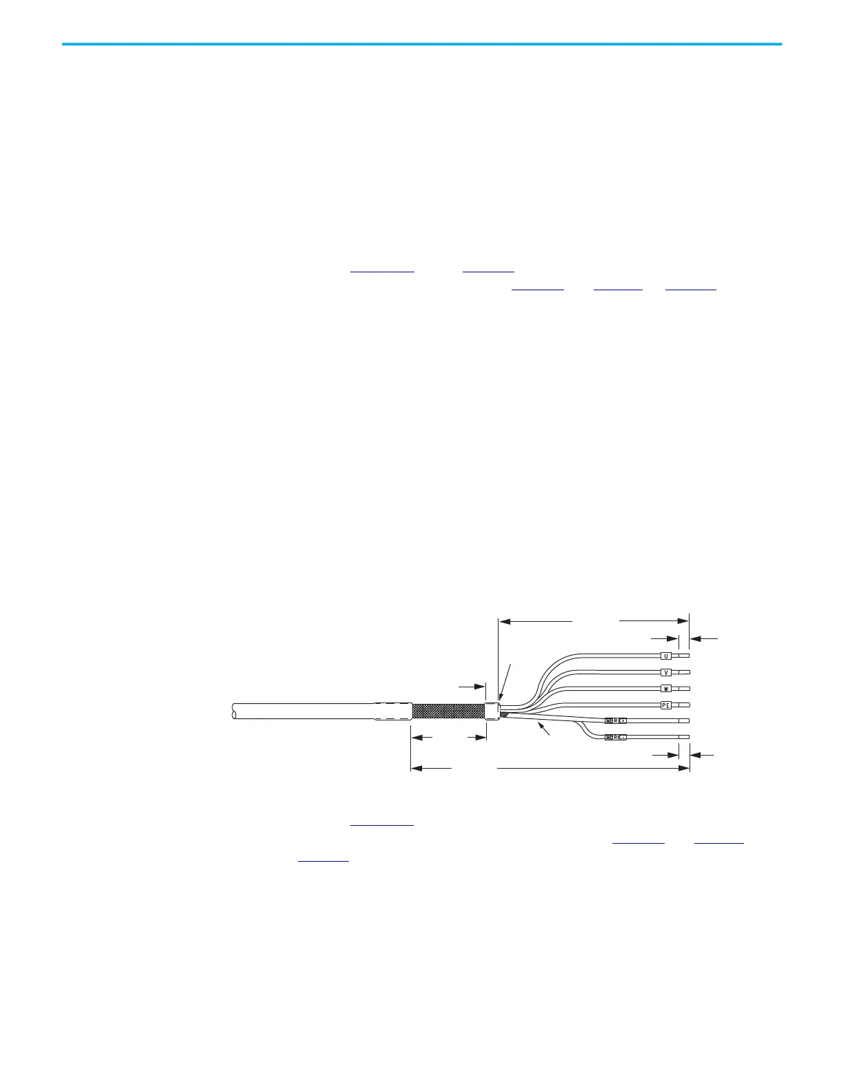
Cable Preparation for 16 and 14 AWG Cables
For dual-axis inverters, the 2090-CPBM7DF power conductor length, 102 mm
(4.0 in.), is sufficiently long to reach the MP connector plug and provides
adequate stress relief. However, you must remove additional insulation from
the power conductors to achieve a strip length of 10 mm (0.39 in.).
The brake conductor length, 635 mm (25 in.), is much longer than necessary.
We recommend that you measure 188 mm (7.4 in.) from the edge of the cable
jacket (that is covered by heat shrink) and trim off the rest.
Refer to Figure 102
and on page 158 for a typical installation example. For strip
lengths and torque values, refer to Table 80
and Table 81 on page 145.
Cable Preparation for 12 and 10 AWG Cables
2090-CPBM7DF (series B) 12 and 10 AWG cables are designed for use with
Kinetix 5700 dual-axis inverters and do not require any modifications.
For dual-axis inverters, 2090-CPBM7DF (series A) 12 and 10 AWG conductors
are too short and stiff to reach the MP connector plug and provide adequate
stress relief.
Follow these steps to prepare your existing (series A) 12 and 10 AWG cables.
1. Remove any heat shrink or small sections of cable jacket from your
existing cable.
2. Remove additional cable jacket and shield braid from your cable
following the diagram below.
Include a new 12 mm (0.5 in.) section of cable jacket and slide it down to
the end of the shield braid.
3. Apply heat shrink to the small section of cable jacket.
Refer to Figure 103
for typical installation examples for series A and series B
cables. For strip lengths and torque values, refer to Table 80
and Table 81 on
page 145
.
7.0 (0.28)
305 (12)
221 (8.7)
10.0 (0.39)
12 (0.50)
71 (2.8)
Dimensions are in mm (in.)
Power Conductors
Brake
Conductors
Compatible Motors and
Actuators
Brake Shield
(trimmed back)
Edge of
Cable Jacket

 Loading...


