296 Rockwell Automation Publication 2198-UM002L-EN-P - October 2021
Chapter 9 Kinetix 5700 Safe Torque-off Function
Safe Torque-off Connector Data
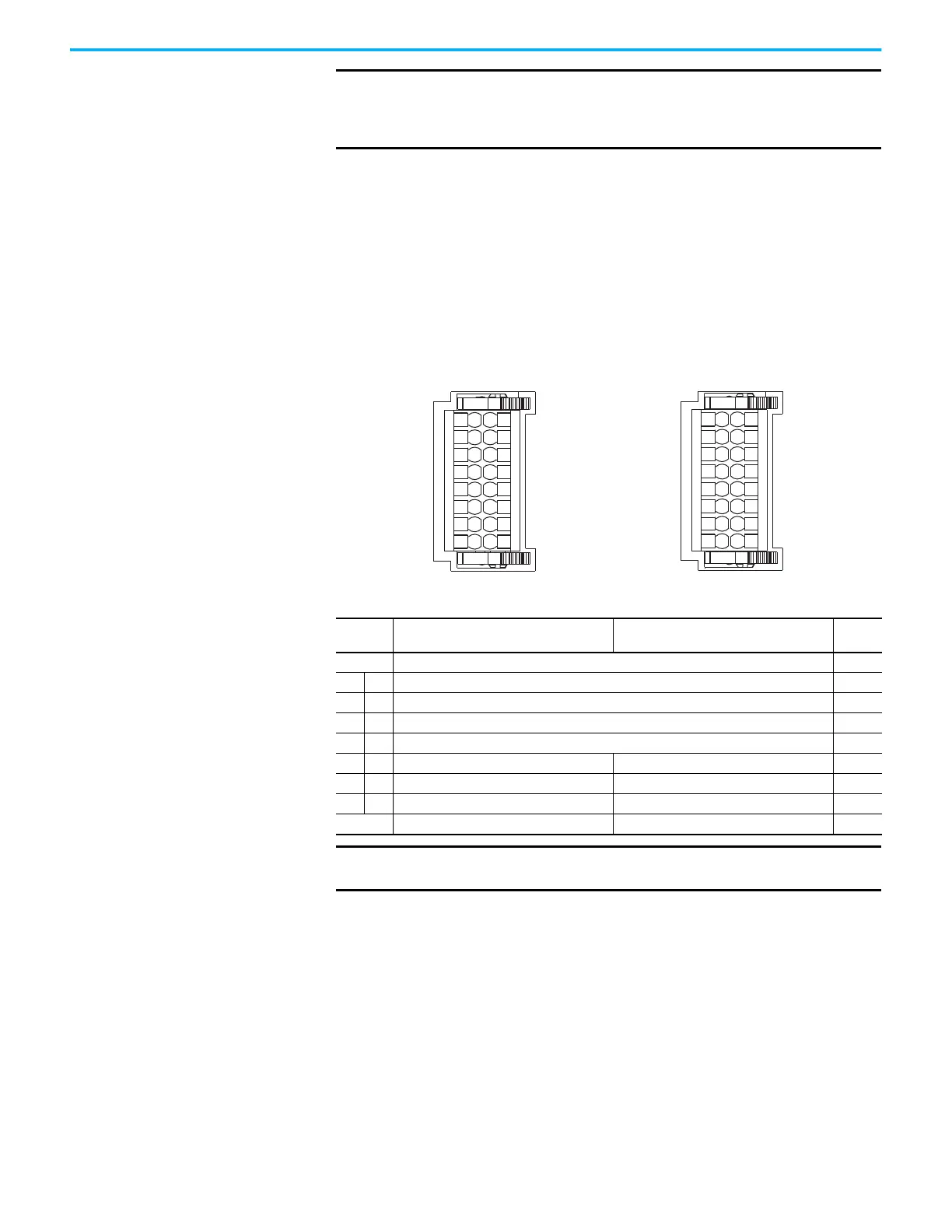
Two rows of eight pins are provided for making drive-to-drive connections.
The dual-axis inverters have pins designated for axis A and axis B. The single-
axis inverters do not use STO-6, -7, -8 and STO-14, -15, -16.
Figure 138 - Pin Orientation for 16-pin Safe Torque-off (STO) Connector
IMPORTANT
The GuardStopInputFault can be reset only if both inputs are in the OFF-
state for more than 1 second. After the fault reset requirement is
satisfied, an MAFR command in the Logix Designer application must be
issued to reset the GuardStopInputFault.
S1A
SCA
S2A
SB-
S1B
SCB
S1A
SCA
S2A
SB-
N/C
N/C
1
2
3
4
5
6
7
8
9
10
11
12
13
14
15
16
1
2
3
4
5
6
7
8
9
10
11
12
13
14
15
16
SB+/NC
S2B
SB+/NC
N/C
2198-Dxxx-ERSx
Dual-axis Inverter
Safety (STO) Connector Plug
2198-Sxxx-ERSx
Single-axis Inverter
Safety (STO) Connector Plug
Table 165 - Safe Torque-off Connector Pinouts
STO Pin
Description
2198-Dxxx-ERSx
Description
2198-Sxxx-ERSx
Signal
1 Safety bypass plus signal. Connect to both safety inputs to disable safe torque-off function. SB+
2 10 Safe stop input channel 1, axis A. S1A
3 11 Safe stop input common, axis A. SCA
4 12 Safe stop input channel 2, axis A. S2A
5 13 Safety bypass minus signal. Connect to safety common to disable safe torque-off function. SB-
6 14 Safe stop input channel 1, axis B. N/C S1B
7 15 Safe stop input common, axis B. N/C SCB
8 16 Safe stop input channel 2, axis B. N/C S2B
9N/C N/C –
IMPORTANT
STO-3 and STO-7 is common for the digital inputs, the safety inputs,
and the encoder power supply (optional).

 Loading...


