Rockwell Automation Publication 2198-UM002L-EN-P - October 2021 131
Chapter 5 Connect the Kinetix 5700 Drive System
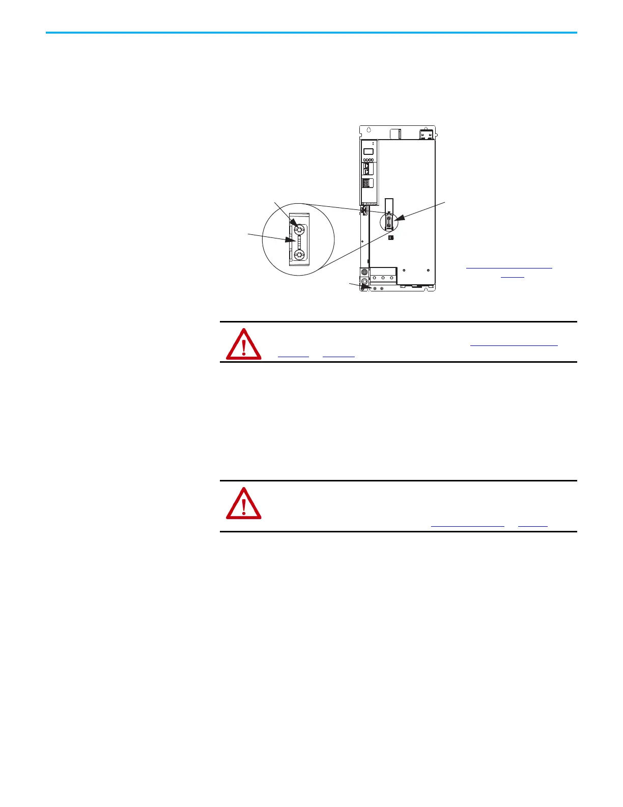
Regenerative bus supplies (catalog numbers 2198-RPxxx) and single-axis
inverters (catalog numbers 2198-S263-ERSx and 2198-S312-ERSx) have a
ground-jumper access door on the front of the unit. Two captive screws secure
the jumper.
Figure 82 - Remove/Install the Ground Jumper
(1) When the regenerative bus supply or 2198-S263-ERSx or 2198-S312-ERSx inverter ground jumper is removed, it can be
permanently stored in threaded holes at the bottom of the chassis.
Ground the Drive System All equipment and components of a machine or process system must have a
common earth-ground point that is connected to chassis. A grounded system
provides a ground path for protection against electrical shock. Grounding your
drive modules and panels minimize the shock hazard to personnel and
damage to equipment caused by short circuits, transient overvoltages, and
accidental connection of energized conductors to the equipment chassis.
Ground the System Subpanel
Ground Kinetix 5700 power supplies, inverters, and accessory modules to a
bonded cabinet ground bus with a braided of at least 10 mm
2
(0.0155 in
2
) in
cross-sectional area. Keep the braided ground strap as short as possible for
optimum bonding.
MOD
NET
2
1
1
I/O
6
5
10
MBRK
+
-
21mm (4 AWG-250 kcmil)
15-20 Nm (132-177 lbin)
2
W V U
Ground Jumper
(1)
Access Door
2198-RPxxx Regenerative Bus Supply
or 2198-S263-ERSx and 2198-S312-ERSx Single-axis Inverter
(single-axis inverter, front view is shown)
Captive Screws (2)
Jumper
TIP
Hold the jumper with
needle-nose pliers and
remove/install the
captive screws.
To determine if you need to remove or
install the ground jumper, see
Ground Screw/Jumper Settings
on page 127
.
Jumper Storage
ATTENTION: Risk of equipment damage exists. The module ground
configuration must be accurately determined. See Ground Screw/Jumper
Settings on page 127.
ATTENTION: The National Electrical Code contains grounding requirements,
conventions, and definitions. Follow all applicable local codes and
regulations to safely ground your system.
For CE grounding requirements, refer to Agency Compliance
on page 37.

 Loading...


