130 Rockwell Automation Publication 2198-UM002L-EN-P - October 2021
Chapter 5 Connect the Kinetix 5700 Drive System
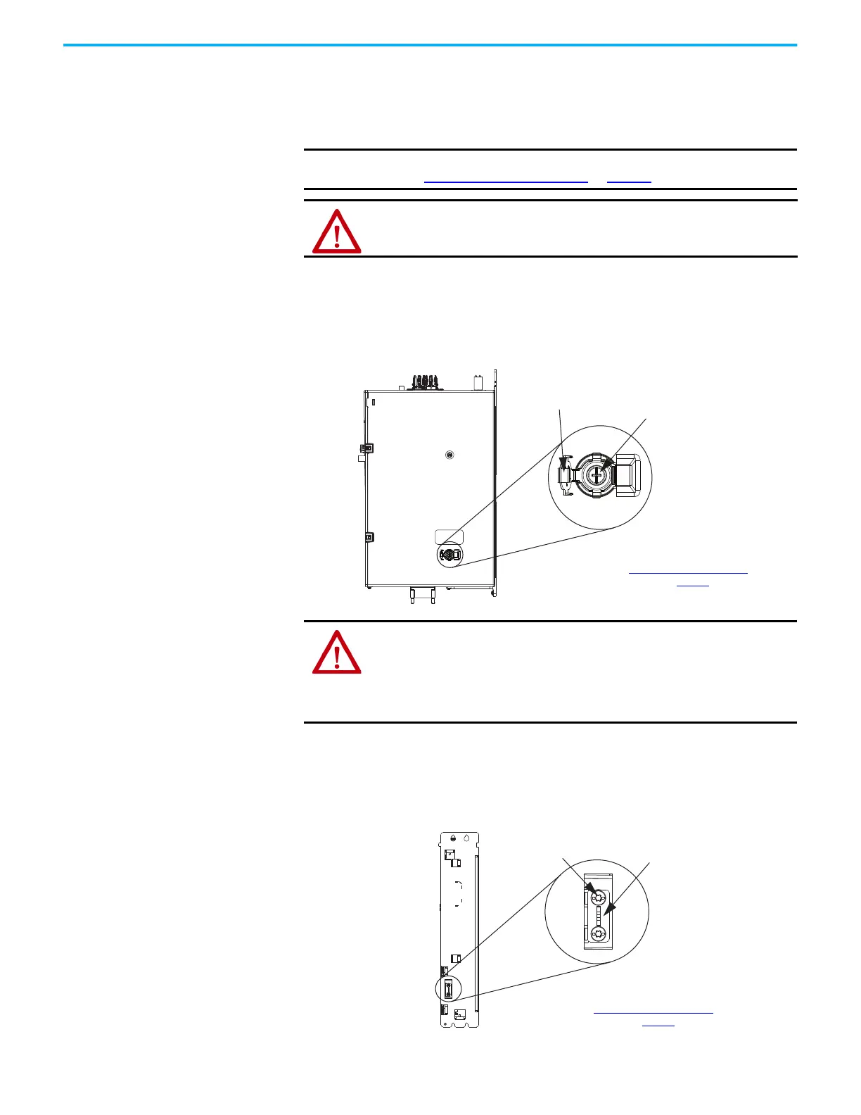
Remove/Install the Ground
Screw/Jumper
We recommend that you remove or install the ground screw/jumper when the
drive module is removed from the panel and placed on its side on a solid work
surface (does not apply to catalog numbers 2198-RPxxx, 2198-S263-ERSx, or
2198-S312-ERSx).
To access or remove/install the ground screw on DC-bus power supplies, dual-
axis inverters, and the iTRAK power supply, open the small plastic door on the
right side of the module.
Figure 80 - Remove/Install the Ground Screw
Single-axis inverters (catalog numbers 2198-S086-ERSx, 2198-S130-ERSx, and
2198-S160-ERSx) have a ground-jumper access door on the back of the unit.
Two captive screws secure the jumper.
Figure 81 - Remove/Install the Single-axis Inverter Ground Jumper
IMPORTANT
To determine if you need to remove or install the ground screw/jumper,
see Ground Screw/Jumper Settings on page 127.
ATTENTION: When the ground screw/jumper is not installed on DC-bus
power supplies, the risk of equipment damage exists because the unit no
longer maintains line-to-neutral or line-to-line voltage protection.
Ground Screw
Access Door
DC-bus Power Supply,
Dual-axis Inverter, or iTRAK Power Supply (side view)
(DC-bus power supply is shown)
Ground Screw
To determine if you need to remove or
install the ground screw, see
Ground Screw/Jumper Settings
on page 127
.
ATTENTION: To avoid personal injury, the ground screw/jumper access
door must be kept closed when power is applied. If power was present and
then removed, wait at least 5 minutes for the DC-bus voltage to dissipate
and verify that no DC-bus voltage exists before accessing the ground
screw/ jumper. This applies to the DC-bus power supply, regenerative bus
supply, dual-axis inverters, and single-axis inverters.
Ground Jumper
Access Door
2198-S086-ERSx, 2198-S130-ERSx, and 2198-S160-ERSx
Single-axis Inverter
(rear view)
Captive Screws (2)
Jumper
TIP
Hold the jumper with
needle-nose pliers and
remove/install the
captive screws.
To determine if you need to remove or
install the ground jumper, see
Ground Screw/Jumper Settings
on page 127
.

 Loading...


