Rockwell Automation Publication 2198-UM002L-EN-P - October 2021 53
Chapter 2 Plan the Kinetix 5700 Drive System Installation
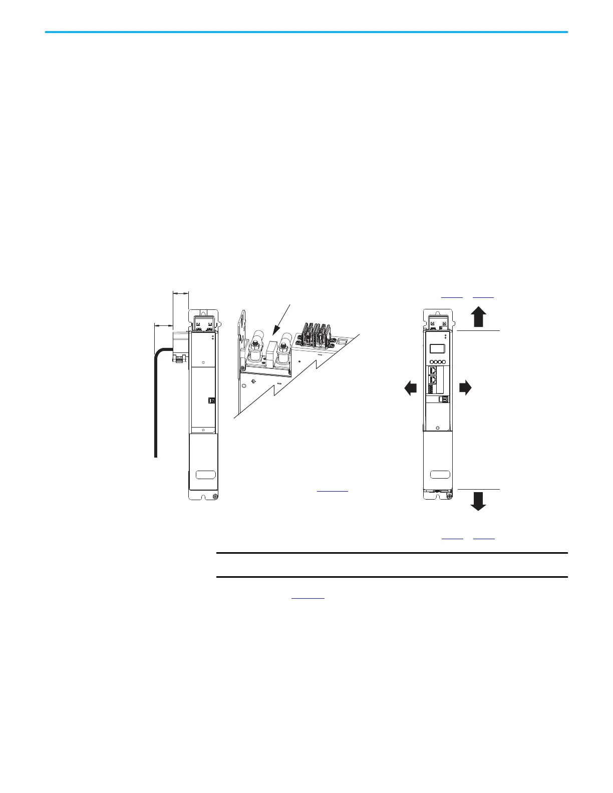
Minimum Clearance Requirements
This section provides information to assist you in sizing your cabinet and
positioning your Kinetix 5700 drive system:
• Additional clearance is required for cables and wires or the shared-bus
connection system connected to the top of the drive modules.
- Accessory modules require extra clearance above for wiring DC-bus
stud connections and installing the cover.
• Additional clearance is required if other devices are installed above and/
or below the drive module and have clearance requirements of their own.
- Accessory modules require extra clearance to route DC-bus wiring into
or away from the drive system.
• Additional clearance left and right of the drive module is required when
mounted adjacent to noise sensitive equipment or clean wire ways.
• The recommended minimum cabinet depth is 300 mm (11.81 in.).
Figure 19 - Minimum Clearance Requirements
See the table on page 54 for clearance specifications.
MOD
NET
2
1
1
4
I/O
MODULE
STATUS
MOD
DC BUS
29.5
(1.16)
Clearance right of the
module is not required.
Clearance left of the
module is not required.
Kinetix 5700 Drive Module
(DC-bus power supply is shown)
Clearance below module
for airflow and installation
(see Table 19
on page 52 for values).
Clearance above module
for airflow and installation
(see Table 19
on page 52 for values).
Refer to the Kinetix 5700, 5500, 5300, and
5100 Servo Drives Specifications Technical
Data, publication KNX-TD003
, for
Kinetix 5700 drive module dimensions.
Kinetix 5700 Accessory Module
(2198-CAPMOD-2240 module is shown)
Clearance above for wiring to DC-bus
studs and lug cover installation.
Clearance where cover and
DC-bus cabling attaches.
IMPORTANT
Mount the drive module in an upright position as shown. Do not mount the module on its
side.

 Loading...


