54 Rockwell Automation Publication 2198-UM002L-EN-P - October 2021
Chapter 2 Plan the Kinetix 5700 Drive System Installation
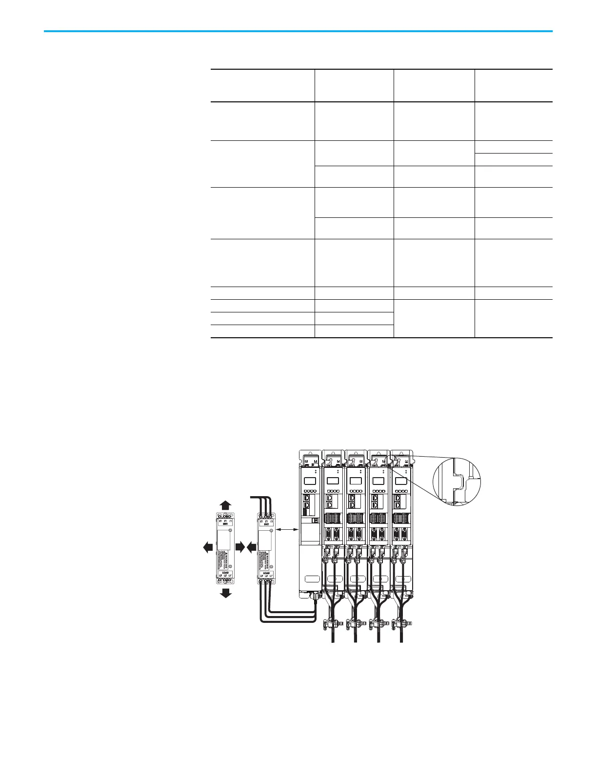
In multi-axis shared-bus configurations, drive modules must be spaced (left to
right) by aligning the zero-stack tab and cutout. Install the AC line filter
(required for CE) with 50 mm (1.97 in.) minimum clearance between the power
supply and filter or between filters, when more than one filter is used.
Minimize the cable length as much as possible.
Figure 20 - Shared-bus and Line Filter Clearance Requirements
(1) Clearance required at the terminals for NEC specified bend radius depends on the wire size in use.
Table 20 - Kinetix 5700 Drive Module Clearance Specifications
Kinetix 5700 Drive Modules
Drive Module
Cat. No.
Clearance Above,
min
mm (in.)
Clearance Below,
(1)
min
mm (in.)
(1) Additional clearance can be required depending on the actual wiring harness being installed.
DC-bus power supply
2198-P031
2198-P070
2198-P141
2198-P208
40 (1.57) 100 (3.94)
Regenerative bus supply
2198-RP088
2198-RP200
40 (1.57)
100 (3.94)
150 (5.91)
2198-RP263
2198-RP312
80 (3.15) 200 (7.87)
Single-axis inverters
2198-S086-ERSx
2198-S130-ERSx
2198-S160-ERSx
40 (1.57) 185 (7.28)
2198-S263-ERSx
2198-S312-ERSx
80 (3.15) 200 (7.87)
Dual-axis inverters
2198-D006-ERSx
2198-D012-ERSx
2198-D020-ERSx
2198-D032-ERSx
2198-D057-ERSx
40 (1.57) 100 (3.94)
iTRAK power supply 2198T-W25K-ER 40 (1.57) 100 (3.94)
Capacitor module 2198-CAPMOD-2240
115 (4.53) 100 (3.94)Extension module 2198-CAPMOD-DCBUS-IO
DC-bus conditioner module 2198-DCBUSCOND-RP312
50 mm
(1.97 in.)
50 mm
(1.97 in.)
50 mm
(1.97 in.)
MOD–
NET–
2
1
1
4
I/O
UFB-A
UFB-B
D+
D-
D+
D-
MF-A
MF-B
2
1
MOD–
NET–
1
2
3
4
5
6
7
8
9
10
1
2
3
4
5
6
7
8
9
10
1
I/O-A
6
510
1
I/O-B
6
510
UFB-A
UFB-B
D+
D-
D+
D-
MF-A
MF-B
2
1
MOD–
NET–
1
2
3
4
5
6
7
8
9
10
1
2
3
4
5
6
7
8
9
10
1
I/O-A
6
510
1
I/O-B
6
510
UFB-A
UFB-B
D+
D-
D+
D-
MF-A
MF-B
2
1
MOD–
NET–
1
2
3
4
5
6
7
8
9
10
1
2
3
4
5
6
7
8
9
10
1
I/O-A
6
510
1
I/O-B
6
510
UFB-A
UFB-B
D+
D-
D+
D-
MF-A
MF-B
2
1
MOD–
NET–
1
2
3
4
5
6
7
8
9
10
1
2
3
4
5
6
7
8
9
10
1
I/O-A
6
510
1
I/O-B
6
510
Zero-stack Tab and
Cutout Aligned
Shared-bus connection system
is not shown for clarity.
Wire Connection
(1)
Terminals
Wire Connection
(1)
Terminals

 Loading...


