132 Rockwell Automation Publication 2198-UM002L-EN-P - October 2021
Chapter 5 Connect the Kinetix 5700 Drive System
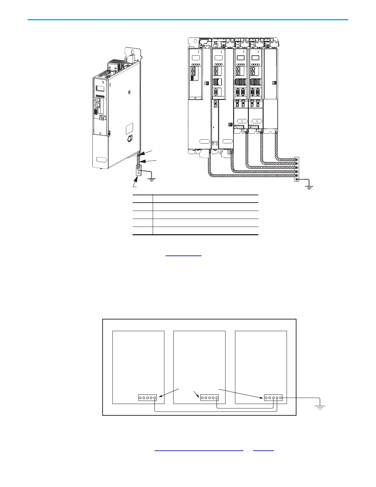
Figure 83 - Connect the Ground Terminal
Refer to the System Design for Control of Electrical Noise Reference Manual,
publication GMC-RM001
, for more information.
Ground Multiple Subpanels
In this figure, the chassis ground is extended to multiple subpanels.
Figure 84 - Subpanels Connected to a Single Ground Point
High-frequency (HF) bonding is not illustrated. For HF bonding information,
refer to HF Bond for Multiple Subpanels
on page 66.
Braided Ground Straps
Provide at least 10 mm
2
(0.0155 in
2
)
in cross-sectional area.
Keep straps as short as possible.
4
3
2
1
DC-bus Power Supply
(typical example)
Kinetix 5700 Drive System
(typical system)
Item Description
1 Ground screw (green) 2.0 N•m (17.7 lb•in), max
2 Braided ground strap (customer supplied)
3 Ground grid or power distribution ground
4 Bonded cabinet ground bus (customer supplied)
Follow NEC and applicable
local codes.
Bonded Ground Bus
Ground Grid or Power
Distribution Ground

 Loading...


