152 Rockwell Automation Publication 2198-UM002L-EN-P - October 2021
Chapter 5 Connect the Kinetix 5700 Drive System
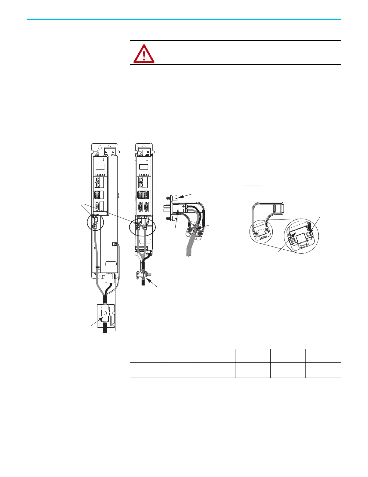
Motor Feedback Connections
Single motor-cable feedback connections are made by using the
2198-KITCON-DSL feedback connector kit.
• 2090-CSxM1DE cables include the connector kit pre-wired to the
feedback conductors.
• 2090-CSxM1DG cables have flying-lead feedback conductors. The 2198-
KITCON-DSL feedback connector kit must be purchased separately and
installed.
Figure 97 - MF Connector Wiring Example
ATTENTION: When routing 2090-CSxM1DE cables through tight spaces, we
recommend removing the 2198-KITCON-DSL feedback connector kit to avoid
causing damage to the kit.
MOD
NET
2
1
1
I/O-A
6
510
1
I/O-B
6
510
UFB-A UFB-B
D+
D-
1
I/O
5
UFB
MOD
NET
2
1
6
10
–
MBRK
+
Motor Cable
Shield Clamp
Motor Feedback
Connector Kits
2198-KITCON-DSL
Feedback Connector Kit
Connector
Housing
Refer to Kinetix 5500 Feedback Connector
Kit Installation Instructions, publication
2198-IN002
, for connector kit specifications.
Internal
Grounding Plate
Clamp Screws (2)
Mounting Screws (2)
Exposed Shield
Feedback Cable
(EPWR+, EPWR-)
Cover
2198-Dxxx-ERSx
Dual-axis Inverters
(2198-D006-ERS4 drive is shown)
Motor Cable
Shield Clamp
2198-Sxxx-ERSx
Single-axis Inverters
(2198-S086-ERS4 drive is
shown)
Table 89 - Motor Feedback (MF) Connector Specifications
Drive Module
Cat. No.
Pin
Signal/
Wire Color
Wire Size
AWG
Strip Length
mm (in.)
Torque Value
N•m (lb•in)
2198-Dxxx-ERSx
2198-Sxxx-ERSx
MF-1 D+/Blue
22 10.0 (0.39) 0.4 (3.5)
MF-2 D-/White/Blue

 Loading...


