256 Rockwell Automation Publication 2198-UM002L-EN-P - October 2021
Chapter 6 Configure and Start the Kinetix 5700 Drive System
5. Click the desired test to verify connections.
6. Click Start.
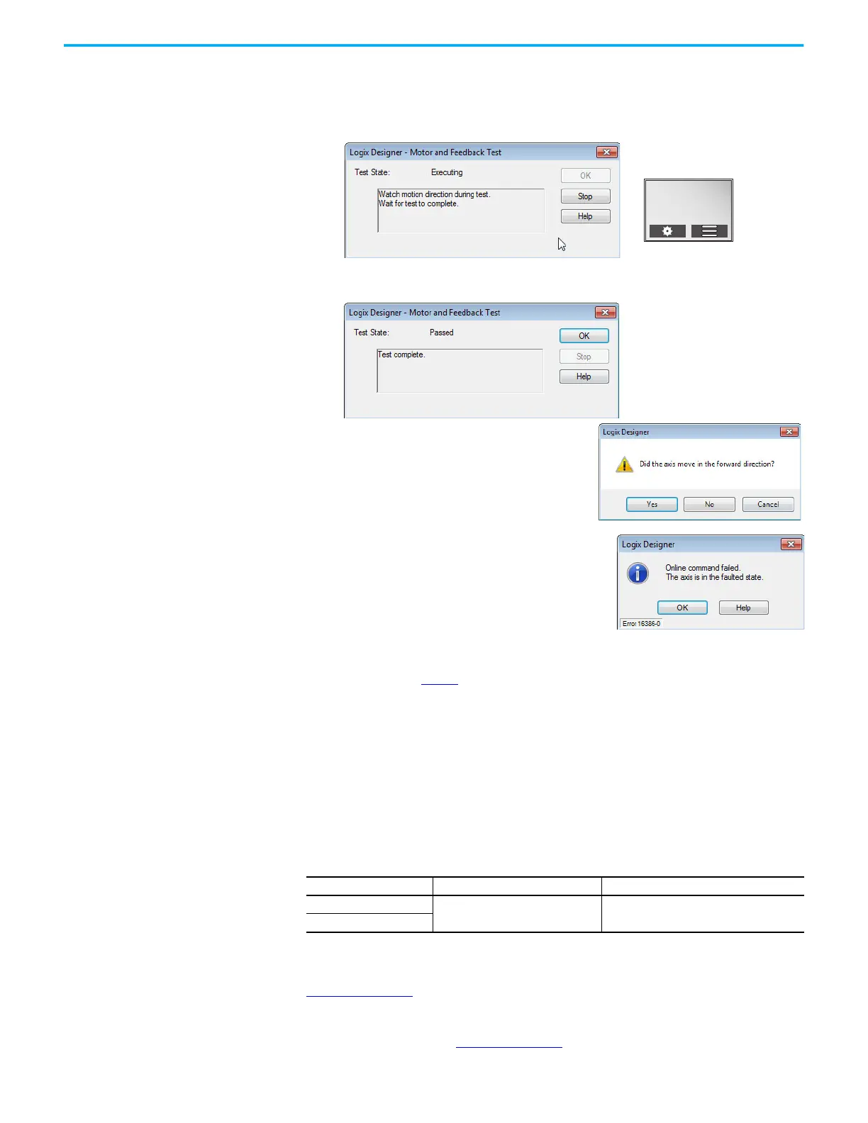
The Logix Designer - Motor and Feedback Test dialog box appears. The
Test State is Executing. TESTING appears on the drive LCD display.
When the test completes successfully, the Test State changes from
Executing to Passed.
7. Click OK.
This dialog box appears asking if the
axis moved in the forward direction.
8. Click Yes if you agree.
9. Click Accept Test Results.
10. If the test fails, this dialog box
appears.
a. Click OK.
b. Verify the DC bus voltage.
c. Verify unit values entered in the
Scaling category.
d. Verify the motor power and feedback wiring.
e. Return to step 5
and run the test again.
Tune the Axes
With Studio 5000 Logix Designer application, version 33 and later, the load
observer and adaptive tuning (tuningless) features are enabled by default for
the following servo drives and drive firmware, so drive configuration is not
required for tuningless operation.
For any other combination of servo drives, drive firmware, or Logix Designer
version, see Tuningless Feature Configuration Quick Start, publication
MOTION-QS001
.
If additional tuning is required, see the Motion System Tuning Application
Technique, publication MOTION-AT005
, for more information.
TESTING
192.168.1.1
DC BUS: 680.0V
Table 126 - For Applications with Tuningless Capability
Drive Cat. No. Drive Firmware Revision Logix Designer Version
2198-xxxx-ERS3 (series B)
13.001 33.00
2198-xxxx-ERS4

 Loading...


