Rockwell Automation Publication 2198-UM002L-EN-P - October 2021 37
Chapter 1 Start
Agency Compliance If this product is installed within the European Union and has the CE mark,
the following regulations apply.
For more information on electrical noise reduction, refer to the System Design
for Control of Electrical Noise Reference Manual, publication GMC-RM001
.
To meet CE requirements, these requirements apply:
• Install an AC line filter (catalog number 2198-DBRxx-F) for input power
with 50 mm (1.97 in.) minimum clearance between the 2198-Pxxx DC-bus
power supply or 2198-RPxxx regenerative bus supply. Minimize the cable
length as much as possible.
• Bond DC-bus power supplies, regenerative bus supplies, inverter
modules, capacitor modules, and line filter grounding screws by using a
braided ground strap as shown in Figure 83 on page 132
.
• When using the 2198-P070 DC-bus power supply above 45 °C (113 °F) with
stranded input power wiring, conductors must be single-core 6 mm
2
stranded copper with 90 °C minimum rating.
• When using the 2198-RP088 regenerative power supply above 40 °C
(104 °F) with stranded input power wiring, conductors must be single-
core 6 mm
2
stranded copper with 90 °C minimum rating.
• Use Kinetix 2090 single motor cables with Kinetix VP motors and
actuators. Use Kinetix 2090 motor power/brake and feedback cables for
other compatible Allen-Bradley motors and actuators. Motor cable
shield-clamp on the drive must be used.
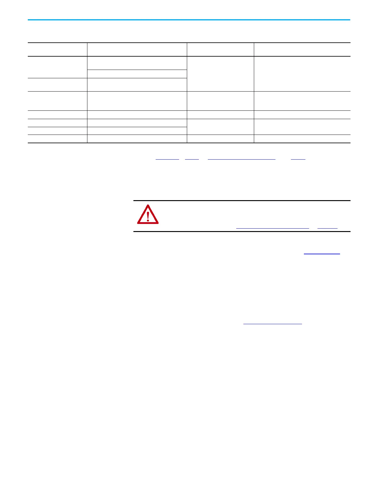
Table 6 - Shared-bus Connector Kit Catalog Numbers
Shared-bus Connector Kits
Cat. No.
Drive Module
Cat. No.
Application Description
2198-TCON-24VDCIN36
(1)
(2)
2198-P031, 2198-P070, 2198-P141, 2198-P208
2198-CAPMOD-2240
24V DC input power to control bus 24V DC input wiring connector2198-RP088, 2198-RP200, 2198-DCBUSCOND-RP312
2198T-W25K-P-IN
(1)
(2)
2198T-W25K-ER, 2198-RP263, 2198-RP312,
2198-S263-ERSx, 2198-S312-ERSx
2198-H040-P-T
2198-D006-ERSx, 2198-D012-ERSx
2198-D020-ERSx, 2198-D032-ERSx
2198-CAPMOD-2240, 2198-DCBUSCOND-RP312
Control power sharing Control power T-connector with bus bars, 55 mm
2198-H070-P-T 2198-D057-ERSx, 2198-S086-ERSx, 2198-S130-ERSx Control power sharing Control power T-connector with bus bars, 85 mm
2198-S160-P-T 2198-S160-ERSx
Control power sharing Control power T-connector with bus bars, 100 mm
2198T-W25K-P-T 2198T-W25K-ER
2198-S312-P-T 2198-S263-ERSx, 2198-S312-ERSx Control power sharing Control power T-connector with bus bars, 220 mm
(1) The input wiring connector can be inserted into any drive module (mid-stream in the drive system) to begin a new 24V control bus when the maximum current value is reached. However, the
input connector must always extend the 24V DC-bus from left to right. The 2198T-W25K-P-IN male plug is physically larger than the male plug on 2198-TCON-24VDCIN36.
(2) For drive module amp ratings and connector wire size information, see Control Power
on page 110, and CP Connector Plug Wiring Specifications table on page 138, respectively.
ATTENTION: Meeting CE requires a grounded system, and the method of
grounding the AC line filter and drive module must match. Failure to do this
renders the filter ineffective and can cause damage to the filter. For
grounding examples, refer to Grounded Power Configurations
on page 121.

 Loading...


