Rockwell Automation Publication 2198-UM002L-EN-P - October 2021 89
Chapter 3 Mount the Kinetix 5700 Drive System
3. Loosely attach the mounting hardware to the panel.
The recommended mounting hardware is M5 (#10-32) steel bolts.
Observe bonding techniques as described in HF Bond for Modules
on
page 64
.
4. Attach the DC-bus supply (or supplies) or the regenerative bus supply to
the cabinet panel.
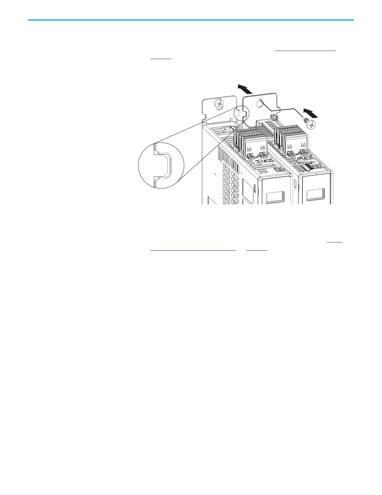
5. Attach additional drive modules to the right or left of the previous
module by using the same method, but also making sure that the zero-
stack tabs and cutouts are engaged.
Zero-stack mounting is required for all configurations. See the Zero-
stack Tab and Cutout Example on page 82.
6. Tighten all mounting fasteners.
Apply 4.0 N•m (35.4 lb•in) maximum torque to each fastener.
Kinetix 5700 Drive System
(DC bus supply and dual-axis
inverter are shown)
Top Screws
(bottom screws not shown)
Zero-stack Tab
and Cutout Engaged

 Loading...


