98 Rockwell Automation Publication 2198-UM002L-EN-P - October 2021
Chapter 4 Connector Data and Feature Descriptions
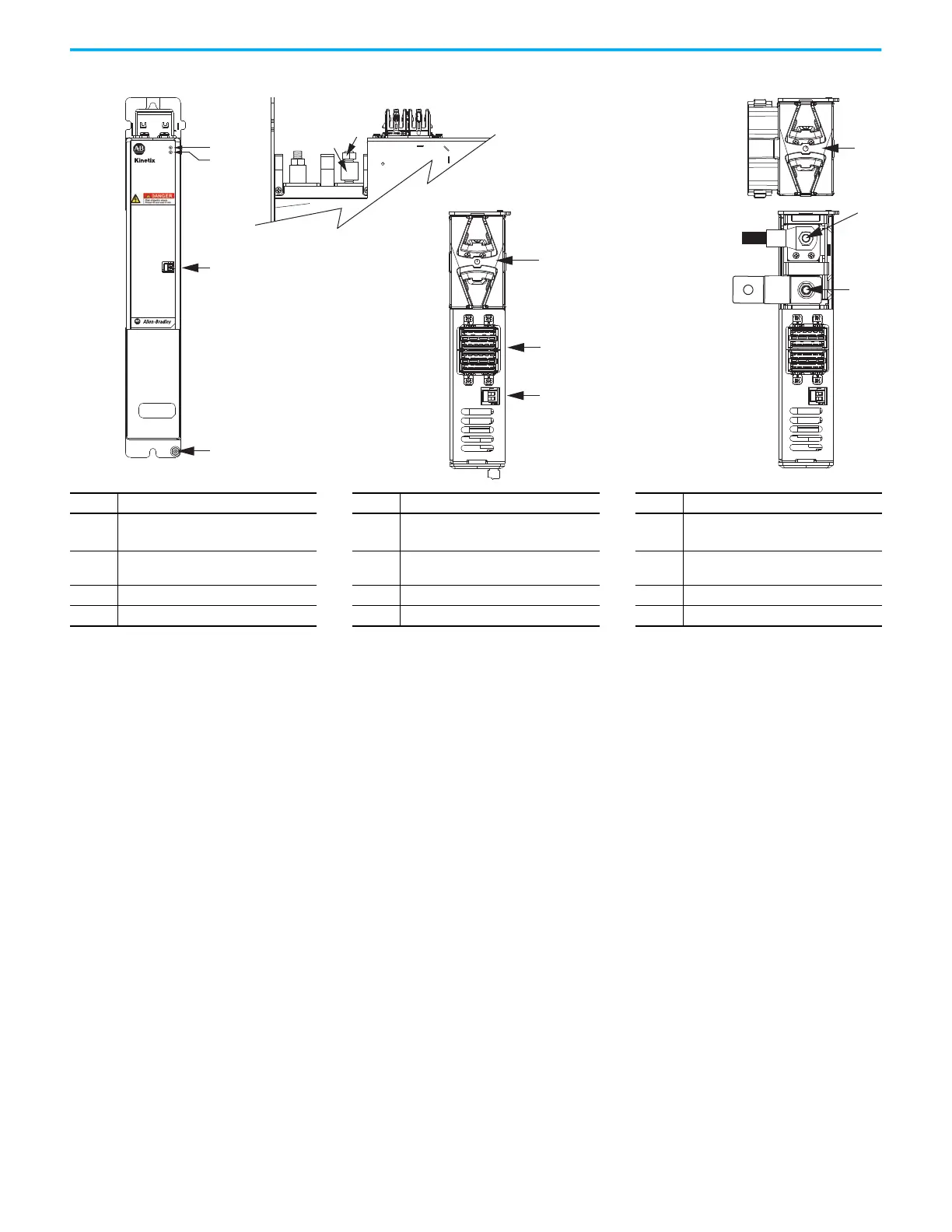
Figure 60 - Capacitor Module and DC-bus Conditioner Module Features and Indicators
Item Description Item Description Item Description
1 Ground stud 5
Stud/lug cover with wires
(1)
9
DC– M8 stud (external DC-bus), shown
with flexible bus-bar
(2)
2 Module status (MS) connector 6 Stud cover without wires 10
DC+ M8 stud (external DC-bus), shown
with wire lug
3 DC-bus status indicator 7 DC-bus (DC) connector 11 M8 hex nut
4 Module status indicator 8 24V control input power (CP) connector 12 Lug spacer
(1) This example shows the lug cover oriented for wires exiting to the left (module is on the far left of the drive configuration). Rotate lug cover 180° when wires exit to the right (module is on
the far right of the drive configuration).
(2) Flexible bus-bars are included with only the 2198-CAPMOD-DCBUS-IO extension module. So, if you have two capacitor modules, two DC-bus conditioner modules, or a capacitor module and
DC-bus conditioner module mounted side by side, you must order the 2198-KITCON-CAPMOD2240 or 2198-KITCON-DCBUSCOND connector set separately.
MODULE
STATUS
MOD
DC BUS
8
24V–
24V+
2
3
4
1
7
6
24V–
24V+
10
9
12
11
5
5700
2198-CAPMOD-2240 Capacitor Module and
2198-DCBUSCOND-RP312 DC-bus Conditioner Module
(front view)
2198-CAPMOD-2240 Capacitor Module and
2198-DCBUSCOND-RP312 DC-bus Conditioner Module
(side view, lug cover removed)
2198-CAPMOD-2240 Capacitor Module and
2198-DCBUSCOND-RP312 DC-bus Conditioner Module
(top views)

 Loading...


