Rockwell Automation Publication 2198-UM002L-EN-P - October 2021 97
Chapter 4 Connector Data and Feature Descriptions
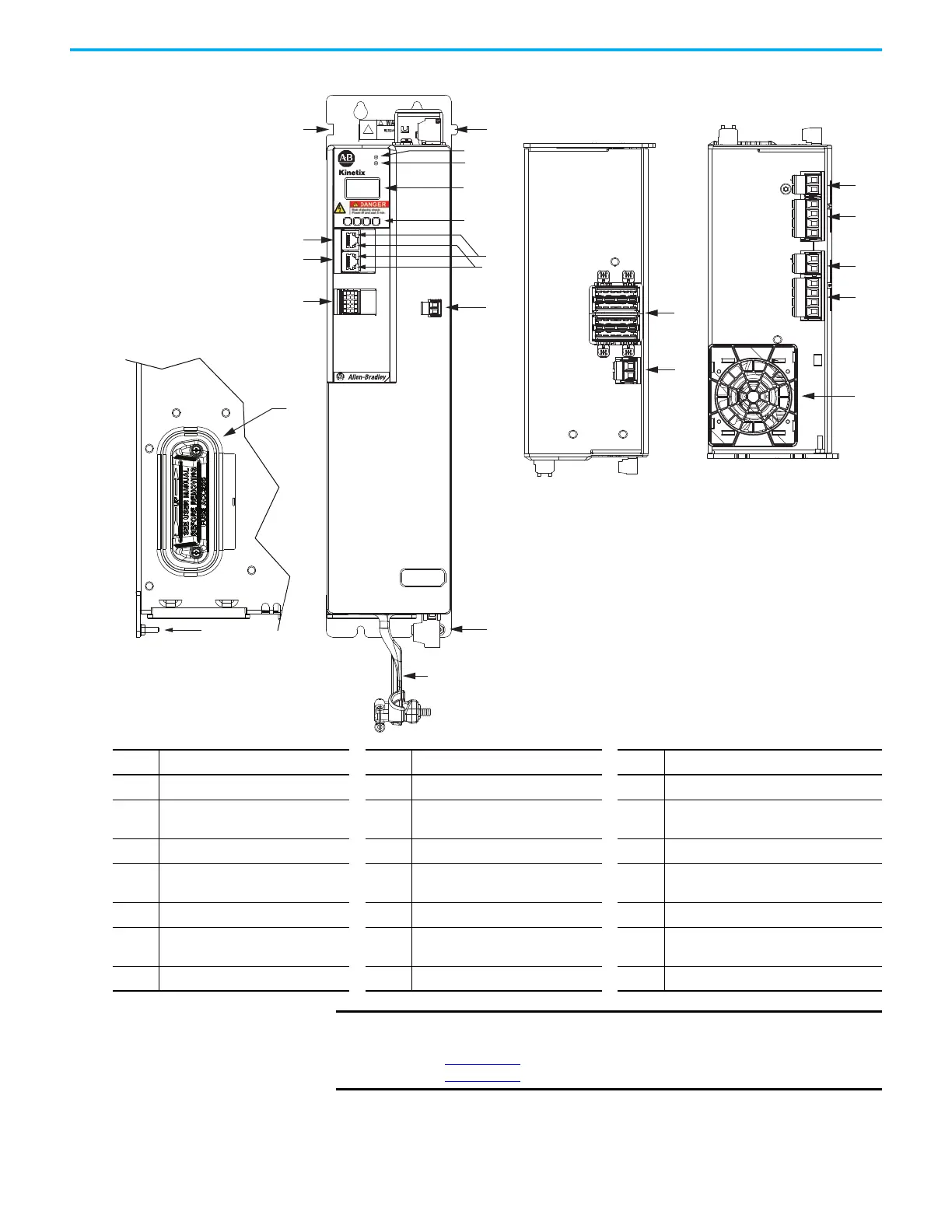
Figure 59 - iTRAK Power Supply Features and Indicators
Item Description Item Description Item Description
1 Power bus cable clamp 8 Network status indicator 15 24V control input power (CP) connector
2
Ground lug (partially obscured behind
output plugs)
9LCD display 16
24V control output power (ICP) connector -
A
3 Digital inputs (IOD) connector 10 Navigation push buttons 17 DC bus output (IDC) connector - A
4 Ethernet (PORT1) RJ45 connector 11 Link speed status indicators 18
24V control output power (ICP) connector -
B
5 Ethernet (PORT2) RJ45 connector 12 Link/Activity status indicators 19 DC bus output (IDC) connector - B
6 Zero-stack mounting tab/cutout 13
iTRAK power-supply ready (IR)
connector
20 Cooling fan
7 Module status indicator 14 DC bus input (DC) connector 21 Power supply internal fuse
2
1
1 6
I/O
510
–
iPS RDY
+
IN 24V -
IN 24V +
DC+
DC-
5700
MOD–
NET–
1
2
3
4
5
6
7
8
9
10
18
16
19
17
20
18
6
7
8
9
4
5
2
3
6
10
12
11
13
1
15
14
21
2
iTRAK Power Supply
(top view)
iTRAK Power Supply
(bottom view)
iTRAK Power Supply
(front view)
iTRAK® Power Supply
(left side view)
IMPORTANT
For IOD, IR, IDC, and ICP connector pinouts, and internal fuse information
see iTRAK System with TriMax Bearings User Manual, publication
2198T-UM002
, or iTRAK 5730 System User Manual, publication
2198T-UM003.

 Loading...


