Rockwell Automation Publication 2198-UM002L-EN-P - October 2021 79
Chapter 3 Mount the Kinetix 5700 Drive System
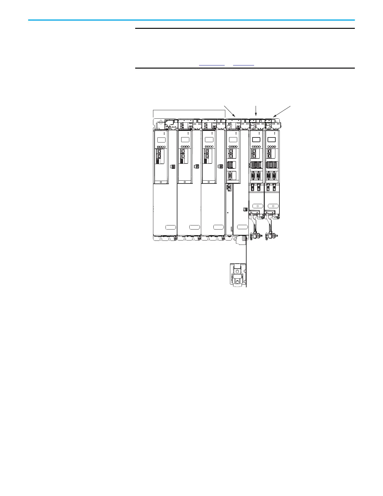
Figure 44 - System Mounting Order Example (multiple DC-bus power supplies)
(1) The DC-bus power supplies can be left or right of the inverters.
IMPORTANT
The maximum number of inverter modules depends on the maximum
system capacitance precharge capability of the power supplies and the
total system capacitance. When there are two or three DC-bus power
supplies, they must be catalog number 2198-P208.
Refer to Appendix C
on page 373 for more system sizing information.
MOD
NET
MOD
NET
MOD
NET
MOD
NET
2
1
1
4
I/O
2
1
2
1
2
1
UFB
UFB-A UFB-B
UFB-A UFB-B
D+
D-
D+
D-
D+
D-
MF-A MF-B MF-A MF-B
D+
D-
MBRK
+
-
MOD
NET
2
1
1
4
I/O
MOD
NET
2
1
1
4
I/O
1
I/O
6
5
10
1
I/O-A
6
510
1
I/O-B
6
510
1
I/O-A
6
510
1
I/O-B
6
510
2198-P208 DC-bus Power Supplies
(1)
Highest Power Utilization
Lowest Power Utilization
2198-S086-ERSx
Single-axis Inverter
2198-D012-ERSx
Dual-axis Inverter
2198-D006-ERSx
Dual-axis Inverter
Shared-bus Connection Systems
(DC-bus and 24V DC)

 Loading...


