80 Rockwell Automation Publication 2198-UM002L-EN-P - October 2021
Chapter 3 Mount the Kinetix 5700 Drive System
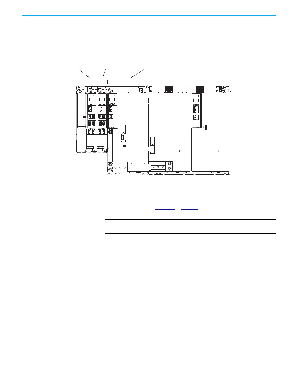
This example is powered by the regenerative bus supply (positioned on the
right) with inverter modules mounted according to power rating (highest to
lowest) from right to left.
Figure 45 - System Mounting Order Example (regenerative bus supply)
(1) The regenerative bus supply can be mounted left or right of the inverters.
MOD
NET
2
1
1
I/O
6
5
10
MBRK
+
-
21mm (4 AWG-250 kcmil)
15-20 Nm (132-177 lbin)
2
W V U
MOD
NET
2
1
1
I/O
6
5
10
MOD
NET
2
1
UFB-A UFB-B
D+
D-
MF-A MF-B
D+
D-
MODULE
STATUS
MOD
DC BUS
1
I/O-A
6
510
1
I/O-B
6
510
L1 L2 L3
21mm (4-4/0 AWG)
15-20 Nm (132-177 lbin)
2
MOD
NET
UFB-A UFB-B
D+
D-
MF-A MF-B
D+
D-
I/O-A
6
10
1
I/O-B
6
510
Dual-axis Inverters
Regenerative Bus Supply
(1)
Single-axis Inverters
Highest Power Utilization
Lowest Power Utilization
2198-S312-ERSx
Single-axis Inverter
2198-D012-ERSx
Dual-axis Inverter
2198-D006-ERSx
Dual-axis Inverter
Shared-bus Connection System
(DC-bus and 24V DC)
2198-DCBUSCOND-RP312
DC-bus Conditioner
IMPORTANT
The maximum number of inverter modules depends on the maximum
system capacitance precharge capability of the power supply and the
total system capacitance.
Refer to Appendix C
on page 373 for more system sizing information.
IMPORTANT
The regenerative bus supply is not compatible with the iTRAK power
supply.

 Loading...


