Rockwell Automation Publication 2198-UM002L-EN-P - October 2021 327
Appendix A Interconnect Diagrams
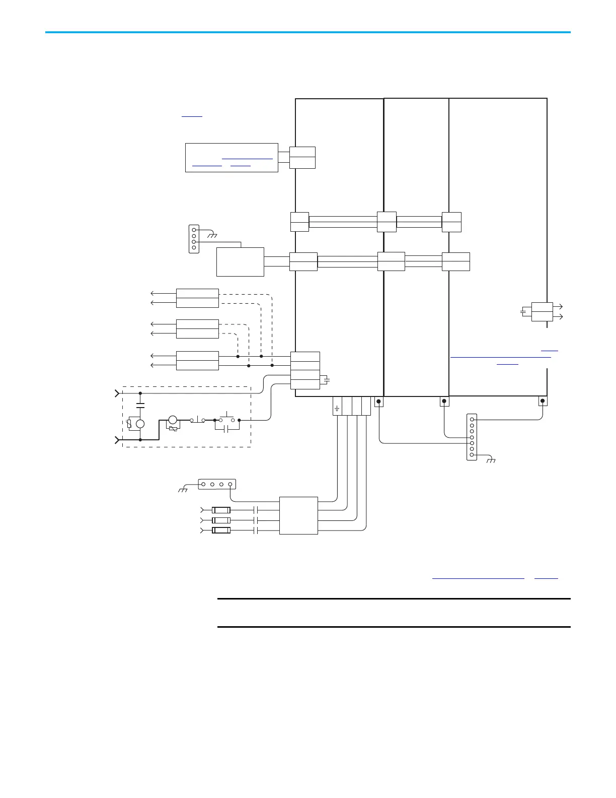
In this example, the 2198-DCBUSCOND-RP312 DC-bus conditioner module is
included because total motor cable length exceeds 400 m (1312 ft).
Figure 165 - Regenerative Bus Supply with DC-bus Conditioner Module
(1) Use 2198-TCON-24VDCIN36 input wiring connector with 2198-RP088 and 2198-RP200 bus supplies. Use 2198T-W25K-P-IN
input wiring connector with 2198-RP263 and 2198-RP312 bus supplies. See CP Connector Wiring - Shared Bus on page 138 for
wiring specifications.
L3 L2 L1
24V_COM
+24V
2
1
DC+
DC-
EN+
EN–
CONV OK+
CONV OK–
DC+
DC–
24V_COM
+24V
DC+
DC-
24V_COM
+24V
DC+
DC-
CONT EN+
CONT EN–
OK+
OK–
24VCOM
Regeneration OK
IOD-40
IOD-41
Kinetix 6200/6500 Drives
Regen_OK+
Regen_OK–
Kinetix 7000 Drives
GPIO-7
GPIO-8
24VCOM
Enable
IOD-3
IOD-2
Kinetix 6000 Drives
MS
MS
2
1
2198-DCBUSCOND-RP312
DC-bus Conditioner Module
Refer to table on page 319 for note information.
2198-RPxxx
Regenerative Bus Supply
2198-Sxxx -ERSx or
2198-Dxxx -ERSx
Inverter
Bonded Cabinet Ground Bus *
Chassis
Customer
Supplied
+24V DC
Power Supply *
STOP *
START *
CR1 *
CR1 *
CR1 *
M1 *
Notes 13,18
24V AC/DC
50/60 Hz
Refer to Attention statement (Note 17).
324…506V AC rms
Three-phase Input
Notes 1, 2
Three-phase Input
(IPD) Connectors
2198-DBRxx-F
Three-phase
AC Line Filter
Note 5
PE Ground
Note 11
PE Ground
Note 11
PE Ground
Note 11
Bonded Cabinet
Ground Bus *
2198-xxxx-P-T
T-connector and Bus Bar
2198-H040-P-T
T-connector and Bus Bar
Shunt Power
(RC) Connector
Bonded Cabinet
Ground Bus *
* Indicates User Supplied Component
Circuit
Protection*
Note 2
Control Power
(CP) Connectors
DC Bus
(DC) Connectors
M1
Contactor
Note 13
Contactor Enable
(CED) Connectors
Note 18
Grounding
Screws/Jumpers
Note 15
Note 8
Module
Status (MS)
Connector
Active Shunt (optional component)
See External Active-shunt
Connections on page 173 for more
Note 27
Monitor DC-bus conditioner module status by
wiring to digital input Bus Conditioner OK or
Logix 5000 controller. Refer to DC-bus
Conditioner Module Status Wiring Example on
page 335
, for an example.
2198-TCON-24VDCIN36
(1)
or 2198T-W25K-P-IN
24V Input Power
Wiring Connector
IMPORTANT
The regenerative bus supply is not compatible with the iTRAK power
supply.

 Loading...


