328 Rockwell Automation Publication 2198-UM002L-EN-P - October 2021
Appendix A Appendix A Interconnect Diagrams
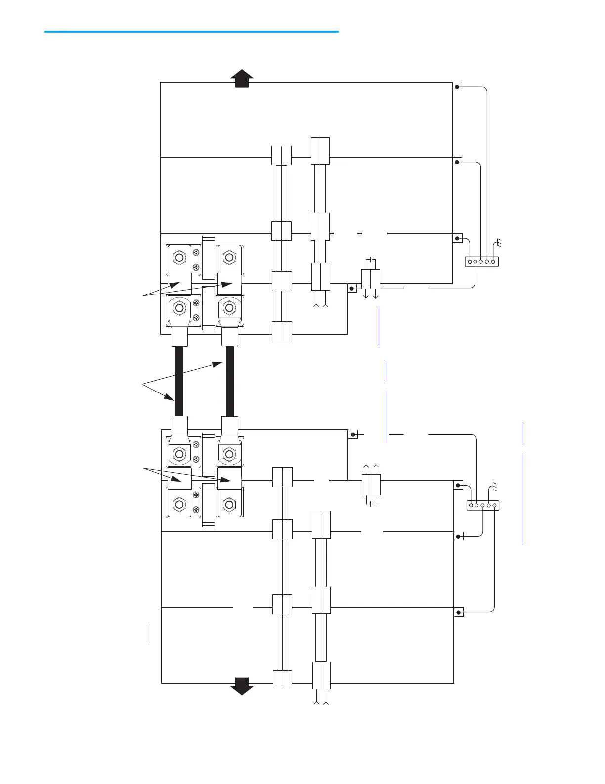
In this example, the 2198-CAPMOD-2240 capacitor module and 2198-CAPMOD-DCBUS-IO extension module are used
for energy storage and to extend the DC-bus voltage to another inverter cluster. The capacitor modules are used alone
when the external DC-bus current is ≤104 A. The extension module (or any combination of two accessory modules) is
needed when the external DC-bus current is >104 A, up to a maximum 208 A.
Figure 166 - Kinetix 5700 Extended Drive System Example (extension module)
(1) Use 2198T-W25K-P-IN input wiring connector with 2198-S263-ERSx and 2198-S312-ERSx drives. Use 2198-TCON-24VDCIN36 input wiring connector with all other drives.
See CP Connector Wiring - Shared Bus
on page 138 for wiring specifications.
2
1
24V_COM
+24V
2
1
DC+
DC-
24V_COM
+24V
DC+
DC-
24V_COM
+24V
DC+
DC-
24V_COM
+24V
DC+
DC-
DC+
DC-
DC+
DC-
24V_COM
+24V
DC+
DC-
24V_COM
+24V
DC+
DC-
MS
MS
MS
MS
2
1
2
1
2198-Sxxx -ERSx or
2198-Dxxx -ERSx
Inverter
PE Ground
Note 11
PE Ground
Note 11
PE Ground
Note 11
Bonded Cabinet Ground
* Indicates User Supplied Component
2198-CAPMOD-DCBUS-IO
Extension Modules
PE Ground
Note 11
PE Ground
Note 11
PE Ground
Note 11
2198-Sxxx -ERSx or
2198-Dxxx -ERSx
Inverter
2198-CAPMOD-2240
Capacitor Module
2198-Sxxx -ERSx or
2198-Dxxx -ERSx
Inverter
2198-Sxxx -ERSx or
2198-Dxxx -ERSx
Inverter
Refer to table on page 319 for note information.
Control Power
(CP) Connectors
DC Bus (DC)
Connectors
Control Power
(CP) Connectors
DC Bus
(DC) Connectors
Bonded Cabinet Ground Bus *
PE Ground
Note 11
PE Ground
Note 11
Flexible Bus-bars
Flexible Bus-bars
User-supplied External DC-bus
Wire Lug Connections
2198-CAPMOD-2240
Capacitor Module
2198-xxxx-P-T
T-connectors
and Bus Bars
Additional Inverters and/or
Kinetix 5700 System Power Supply
Additional Inverters
2198-TCON-24VDCIN36
or 2198T-W25K-P-IN
24V Input Power
Wiring Connector
(1)
2198-TCON-24VDCIN36
24V Input Power
Wiring Connector
Note 8
Note 8
Note 8
Note 8
Module
Status (MS)
Connector
Module
Status (MS)
Connector
Monitor capacitor module status by wiring to digital input Bus
Capacitor OK or Logix 5000 controller. Refer to Capacitor Module
Status Wiring Example on page 335, for an example.
ATTENTION: Circuit protection can
be added after the power supply
cluster to help protect converters
and inverters from damage due to
a DC-bus cable short-circuit.
2198-H040-P-T
T-connector
and Bus Bar
2198-xxxx-P-T
T-connectors
and Bus Bars
2198-xxxx-P-T
T-connectors
and Bus Bars

 Loading...


