170 Rockwell Automation Publication 2198-UM002L-EN-P - October 2021
Chapter 5 Connect the Kinetix 5700 Drive System
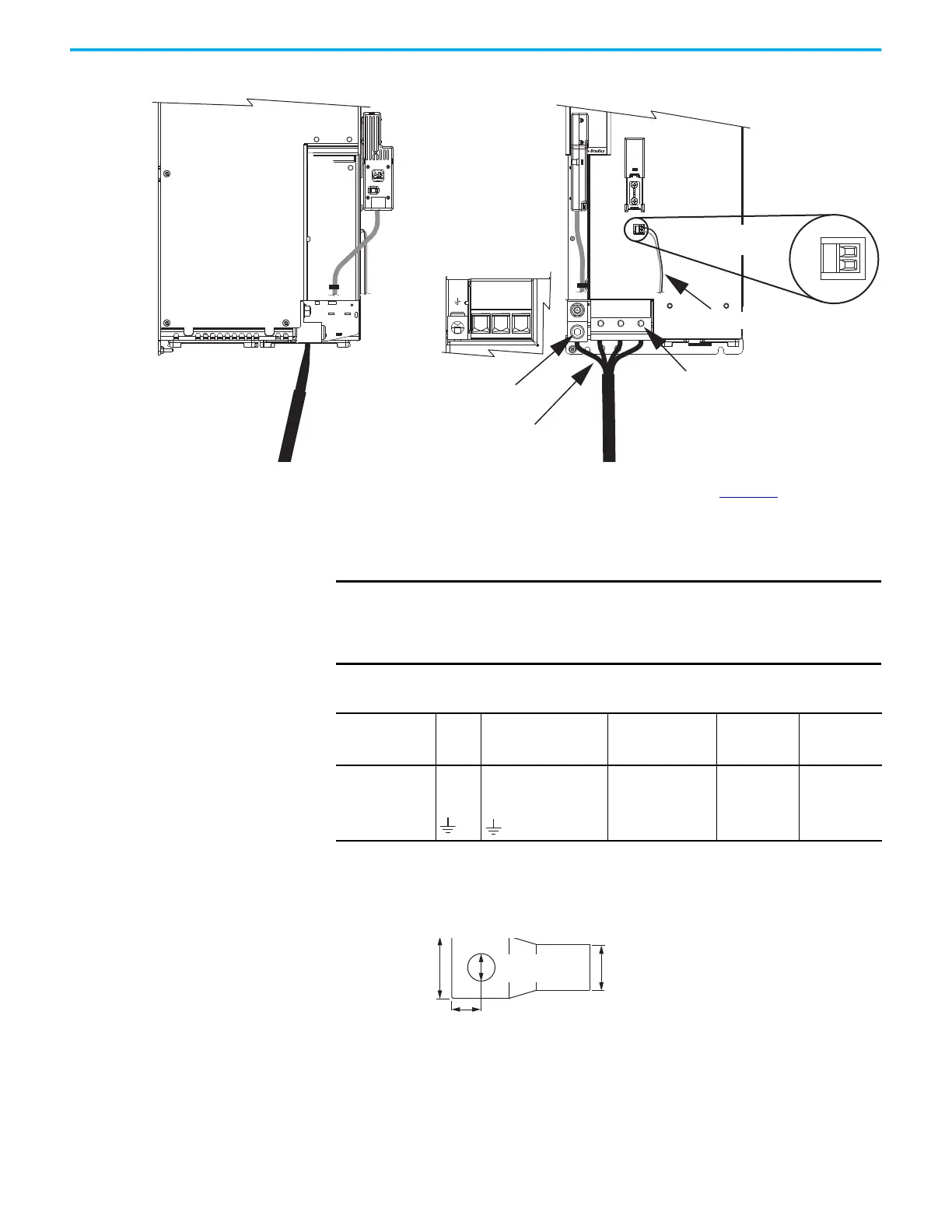
Figure 112 - MP and BC Connector Wiring (single-axis inverters)
Prepare the customer-supplied motor power cable (see page 169), then attach
motor power and ground wires to the motor power connector and ground
terminal. Plug in motor feedback and brake connectors, as required for your
application.
If you replace the ground-conductor termination block with a lug, the lug size
must not exceed these maximum dimensions.
Figure 113 - Maximum Customer-supplied Lug Dimensions
MBRK
+
-
21mm (4 AWG-250 kcmil)
15-20 Nm (132-177 lbin)
2
W V U
W V U
2
1
–
MBRK
+
Motor Cable
Connections
Motor Brake
(BC) Connector Plug
2198-S263-ERSx or
2198-S312-ERSx
Single-axis Inverters
(front view)
Motor Power
(MP) Connector
(bottom view)
Motor Power (MP) Connector
Screws (3x): 6 mm Hex Driver
Torque: 15…20 N•m (132…177 lb•in)
Motor Power Ground Terminal
Screw: 8 mm Hex Driver
Torque: 5.6 N•m (50 lb•in)
2198-S263-ERSx or
2198-S312-ERSx
Single-axis Inverters
(side view)
Customer-supplied Motor Power Cable
2198-K57CK-D15M
Motor Feedback
Connector Kit
Customer-supplied Motor Brake Cable
IMPORTANT
The supplied ground terminal is suitable for use with 16…120 mm
2
(6 AWG…250 kcmil) Class B and C power cables and all Allen-Bradley
Kinetix 2090 motor cables. A customer-supplied lug is required for all
other applications.
Table 101 - Motor Power Connector Specifications (single-axis inverters)
Drive Module
Cat. No.
Pin Signal/Wire Color
Recommended Wire
Size
mm
2
(AWG)
Strip Length
mm (in.)
Terminal
Torque Value
N•m (lb•in)
2198-S263-ERSx
2198-S312-ERSx
21.1…120
(4…250 kcmil)
27.0 (1.06)
15…20
(132…177)
Brown
Black
Blue
Green/Yellow
U
V
W
25.4 mm
(1.00 in.)
11.43 mm
(0.45 in.)
Lug size according to cable size and
classification. Flexible wires (Class K…G)
must use flex-rated lugs.
8 mm (0.315 in.)
(inside diameter hole)

 Loading...


