134 Rockwell Automation Publication 2198-UM002L-EN-P - October 2021
Chapter 5 Connect the Kinetix 5700 Drive System
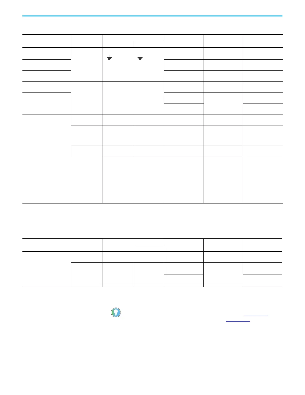
Table 71 - Regenerative Bus Supply Wiring Requirements
Regen Bus Supply
Cat. No.
Description
Connects to Terminals
Wire Size
mm
2
(AWG)
Strip Length
mm (in.)
Torque Value
N•m (lb•in)
Pin Signal
2198-RP088
Mains input power
6…10
(1)
(10…8)
10.0 (0.39)
0.5…0.8
(4.4…7.1)
2198-RP200
10…35
(8…2)
20.0 (0.79)
2.5…4.5
(22…40)
2198-RP263
2198-RP312
21.1…120
(4…250 kcmil)
27.0 (1.06)
15…20
(132…177)
2198-RP088
2198-RP200
PELV/SELV
24V power
(connector plug)
CP-1
CP-2
24V+
24V–
0.5…4
(20…12)
7.0 (0.28)
0.22…0.25
(1.9…2.2)
2198-RP263
2198-RP312
1.5…4
(16…12)
10.0 (0.39)
0.5…0.6
(4.4…5.3)
6 (10)
0.7…0.8
(6.1…7.0)
2198-RPxxx
DC Bus power Bus bar
DC–
DC+
N/A
(2)
N/A
(3)
N/A
(3)
Contactor enable
OK+
OK–
EN–
EN+
CONV OK+
CONV OK–
CONT EN–
CONT EN+
0.14…2.5
(26…12)
7.0 (0.28)
0.4…0.5
(3.5…4.4)
Active shunt
RC-2
RC-1
DC+
DC–
1.5…6
(16…10)
12.0 (0.47)
0.5…0.6
(4.5…5.3)
Digital inputs
IOD-1
IOD-2
IOD-3
IOD-4
IOD-5
IOD-6
IOD-7
IOD-8
IOD-9
IOD-10
IN1
COM
IN2
COM
SHLD
IN3
COM
IN4
COM
SHLD
0.14…1.5
(26…16)
10.0 (0.39)
N/A
(3)
(1) Applies to solid wire. If using stranded wire, the maximum wire size is 6 mm
2
(10 AWG). To meet CE requirements above 40 °C (104 °F) for 6 mm
2
stranded wires, single-core copper
conductors must be used with 90 °C minimum rating.
(2) Shared DC-bus power connections are always made from drive to drive over the bus-bar connection system. These terminals do not receive discrete wires.
(3) This connector uses spring tension to hold wires in place.
Table 72 - iTRAK Power Supply Wiring Requirements
iTRAK Power Supply
Cat. No.
Description
Connects to Terminals
Wire Size
mm² (AWG)
Strip Length
mm (in.)
Torque Value
N•m (lb•in)
Pin Signal
2198T-W25K-ER
DC-bus input
power
Bus bar
DC–
DC+
N/A
(1)
N/A
(1)
N/A
(1)
SELV/PELV rated
24V power
(connector plug)
CP-1
CP-2
24V+
24V–
1.5…4
(2)
(16…12)
10.0 (0.39)
0.5…0.6
(4.4…5.3)
6 (10)
(2)
0.7…0.8
(3)
(6.1…7.0)
(1) Shared DC-bus power connections are always made from power supply to power supply over the bus-bar connection system. These terminals do not receive discrete wires.
(2) Use sufficient wire size to support the complete control power load, including the Kinetix 5700 drive modules and pass-through current for the attached motor modules.
(3) Depending on 24V current demand, 6 mm
2
(10 AWG) wire can be required. When 6 mm
2
(10 AWG) wire is used, these torque specifications apply.
For iTRAK power supply wiring requirements not shown here, see iTRAK
System with TriMax Bearings User Manual, publication 2198T-UM002, or
iTRAK 5730 System User Manual, publication 2198T-UM003
.

 Loading...


