148 Rockwell Automation Publication 2198-UM002L-EN-P - October 2021
Chapter 5 Connect the Kinetix 5700 Drive System
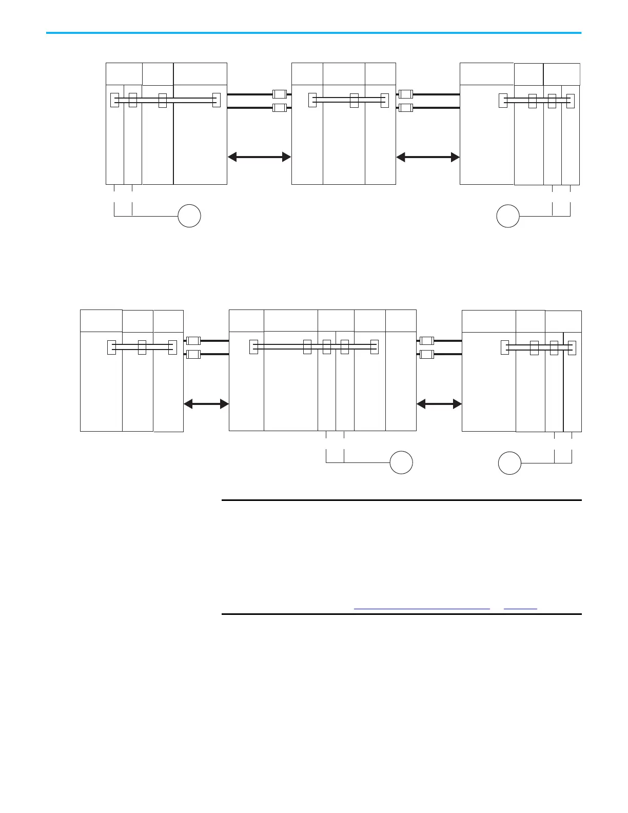
Figure 95 - Regenerative Bus Supply Example/Center Power Supply Cluster/104 A, max
(1) The National Electrical Code and local electrical codes take precedence over the values and methods provided.
When the power supply is positioned right or left of the extended clusters, the
maximum total DC-bus cable length is 70 m (230 ft).
Figure 96 - Regenerative Bus Supply Example/Two Extended Clusters/208 A, max
(1) The National Electrical Code and local electrical codes take precedence over the values and methods provided.
2198-CAPMOD-2240
2198-Sxxx-ERSx
2198-Sxxx-ERSx
M
90 m (295 ft) x 2 axes = 180 m (591 ft)
2198-Sxxx-ERSx
2198-Sxxx-ERSx
2198-CAPMOD-2240
M
90 m (295 ft) x 2 axes = 180 m (591 ft)
2198-DCBUSCOND-RP312
2198-CAPMOD-DCBUS-IO
DC+
DC–
DC+
DC–
70 m
(230 ft),
max
70 m
(230 ft),
max
Capacitor
Module
Capacitor
Module
Single-axis
Inverters
Regenerative
Bus Supply
2198-RPxxx
(power supply cluster)
Cluster #2
2198-DCBUSCOND-RP312
(extended cluster)
Cluster #3
DC-bus Conditioner
Module
Single-axis
Inverters
Capacitor
Module
DC-bus Conditioner
Module
DC Bus
2198-CAPMOD-2240
(extended cluster)
Cluster #1
Motor Array
Motor Array
Extension
Module
DC Bus
Circuit
(1)
Protection
(optional)
Circuit
(1)
Protection
(optional)
2198-CAPMOD-2240
2198-Sxxx-ERSx
2198-Sxxx-ERSx
2198-CAPMOD-2240
M
90 m (295 ft) x 2 axes = 180 m (591 ft)
2198-CAPMOD-DCBUS-IO
2198-Sxxx-ERSx
2198-Sxxx-ERSx
2198-CAPMOD-2240
M
90 m (295 ft) x 2 axes = 180 m (591 ft)
2198-DCBUSCOND-RP312
2198-CAPMOD-DCBUS-IO
DC+
DC–
35 m
(115 ft)
DC+
DC–
35 m
(115 ft)
Capacitor
Module
DC Bus
Capacitor
Module
DC Bus
Single-axis
Inverters
Regenerative
Bus Supply
2198-RPxxx
(power supply cluster)
Cluster #1
2198-DCBUSCOND-RP312
(extended cluster)
Cluster #3
DC-bus Conditioner
Module
Extension
Module
Extension
Module
Single-axis
Inverters
Capacitor
Module
DC-bus Conditioner
Module
DC Bus
2198-CAPMOD-DCBUS-IO
(extended cluster)
Cluster #2
Motor Array
Extension
Module
Circuit
(1)
Protection
(optional)
Circuit
(1)
Protection
(optional)
IMPORTANT
It is important to use low-inductance DC cable routing to help reduce the
risk of voltage oscillations between clusters.
Low-inductance DC cable routing can be achieved by means of positive
and negative cables routed in parallel and as close to one another as
possible, less than 0.3 m (1.0 ft).
Size the DC cable in accordance with UL or applicable agency guidelines.
The voltage drop across the DC cable can be further reduced by using a
bigger cable size because voltage drop is directly proportional to cable
resistance (see Recommended DC-bus Cable Gauge
on page 149).

 Loading...


