198 Rockwell Automation Publication 2198-UM002L-EN-P - October 2021
Chapter 6 Configure and Start the Kinetix 5700 Drive System
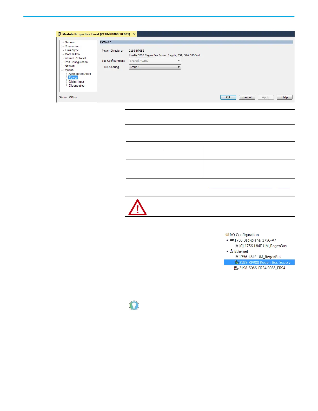
5. Click the Power category.
6. From the pull-down menus, choose the power options appropriate for
your hardware configuration.
7. Click OK to close the New Module dialog box.
8. Your 2198-RPxxx regenerative bus supply
appears in the Controller Organizer
under the Ethernet network in the I/O
Configuration folder.
9. Click Close to close the Select Module
Type dialog box.
10. Right-click the regenerative bus supply you just created in the Controller
Organizer and choose Properties.
The Module Properties dialog box appears.
IMPORTANT
The Logix Designer application enforces shared-bus
configuration rules for Kinetix 5700 drives.
Attribute Menu Description
Bus Configuration
Shared AC/DC
(1)
(1) Shared AC/DC bus configuration is the default selection for regenerative bus supplies.
Applies to 2198-RPxxx regenerative bus supply modules.
Bus Sharing Group
(2)
(2) For more information on bus-sharing groups, refer to Understand Bus-sharing Group Configuration on page 251.
•Group1
•Group2
• Group3…
Applies to any bus-sharing configuration.
ATTENTION: To avoid damage to equipment all modules physically
connected to the same shared-bus connection system must be part
of the same Bus Sharing Group in the Logix Designer application.
To configure the remaining regenerative bus supply properties,
you must close the New Module dialog box and reopen it as the
Module Properties dialog box.

 Loading...


