218 Rockwell Automation Publication 2198-UM002L-EN-P - October 2021
Chapter 6 Configure and Start the Kinetix 5700 Drive System
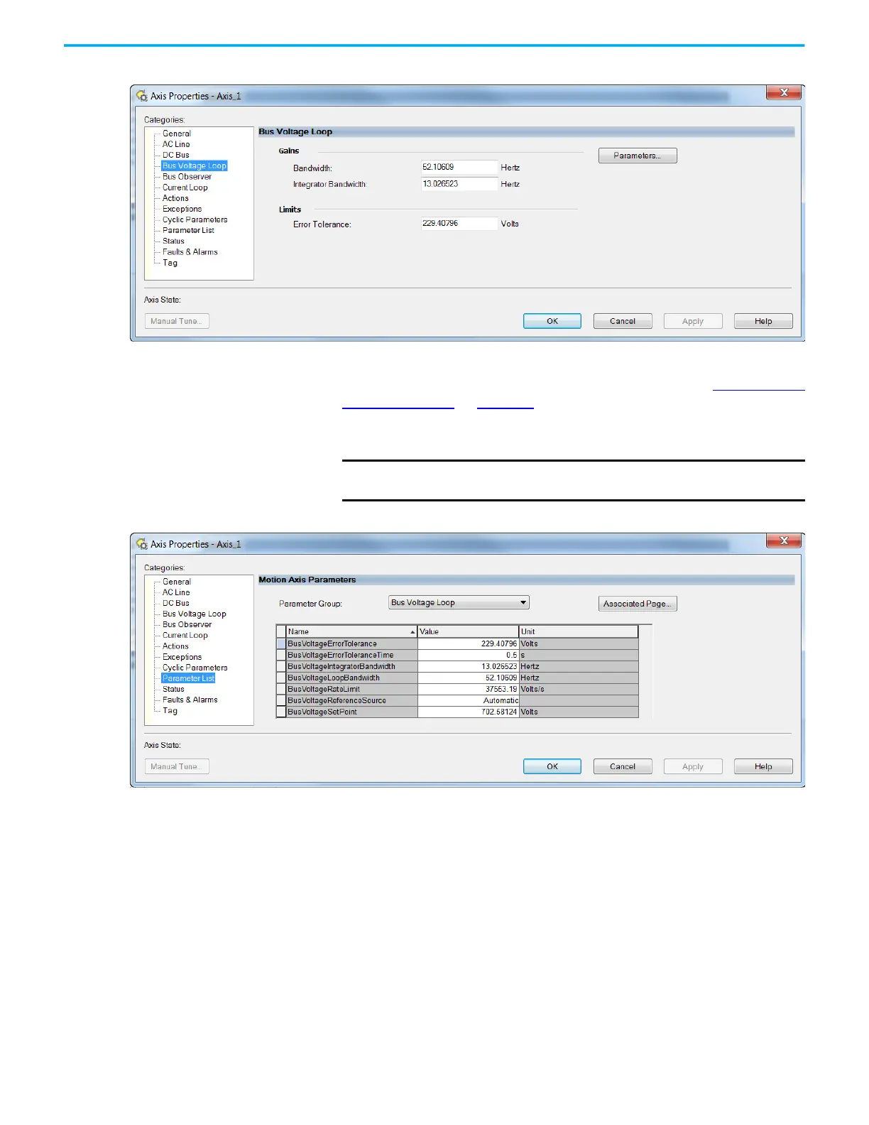
9. Click the Bus Voltage Loop category.
We do not recommend changing the default bandwidth values.
The default Gains are set to support peak load current. See Detuned Gain
Setting Examples on page 220 for an example of a detuned gain set.
Detuned gains increase system stability and can improve THD, but
voltage regulation will be less stiff.
10. Click Parameters.
With the default BusVoltageRateLimit, if the BusVoltageSetPoint value
changes (while running) the power supply will draw peak current to
change the bus voltage as fast as possible. You can reduce the rate limit to
limit the current during changes to the BusVoltageSetPoint attribute
without any effect to stability or load response.
IMPORTANT
Reduced voltage regulation stiffness can result in overvoltage or
undervoltage faults during peak load.

 Loading...


