24 Rockwell Automation Publication 2198-UM002L-EN-P - October 2021
Chapter 1 Start
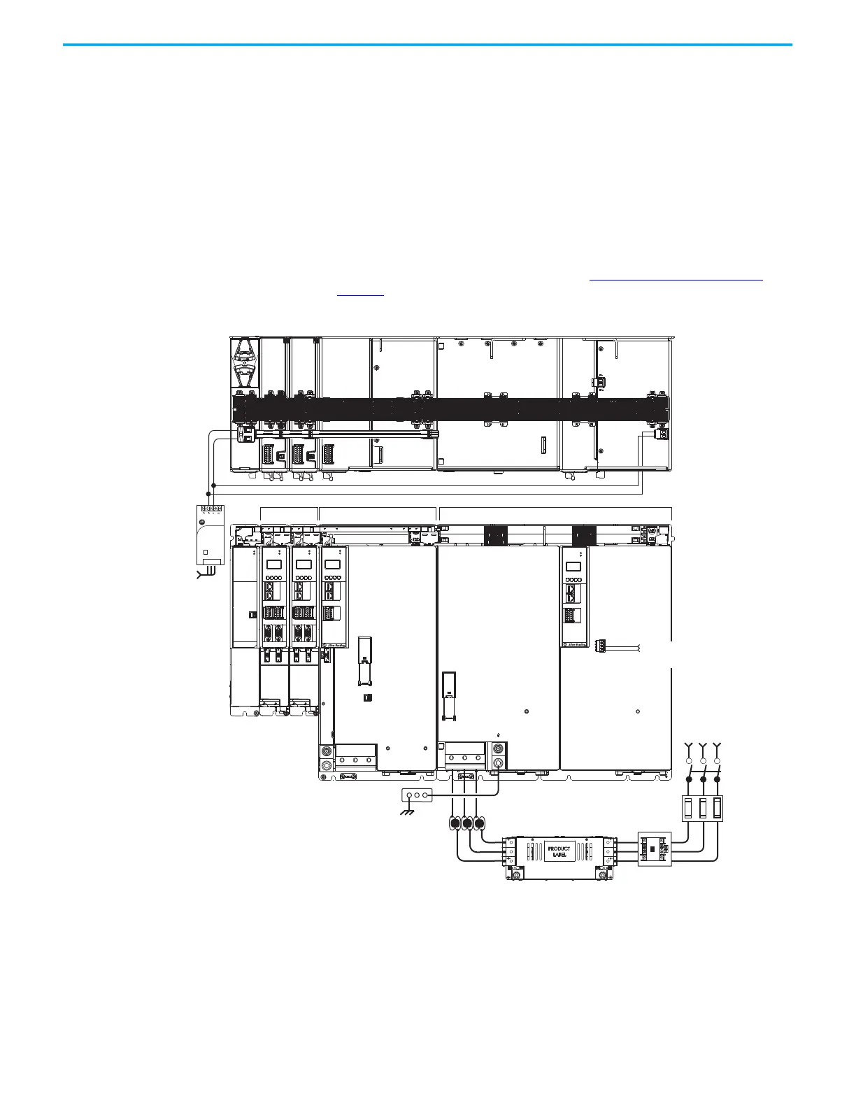
In this example, the 2198-RP312 regenerative bus supply is mounted on the far
right and followed by the 2198-S312-ERSx single-axis inverter, and two
2198-D020-ERSx dual-axis inverters.
• The 2198-BARCON-440DC200 DC-bus link extends the DC-bus from the
regenerative bus supply to the single-axis inverter.
• The 2198-BARCON-220DC200 DC-bus link extends the DC-bus from the
single-axis inverter to the dual-axis inverter.
• The regenerative bus supply has 24V DC wired to the connector plug
•The 2198-xxxx-P-T bus-bar connector extends 24V control power from
the input wire connector to the dual-axis and single-axis inverters.
• The DC-bus conditioner module is required when the combined motor
cable length exceeds 400 m (1312 ft). See Accessory Module Selection
on
page 56 for more information on accessory module requirements.
Figure 6 - Typical Shared DC-bus Installation (mounted right to left)
(1) The regenerative bus supply can be left or right of the inverters. Further, we recommend that the highest inverter power
ratings are positioned closest to the regenerative bus supply and in decreasing order leading away from the regenerative
bus supply.
19
8
16
SB+/NC
NC
S1A
SCA
S2A
SB-
NC
NC
1606-XL
Power Supply
Input
Allen-Bradley
MOD
NET
2
1
1
I/O
6
5
10
MBRK
+
-
21mm (4 AWG-250 kcmil)
15-20 Nm (132-177 lbin)
2
W V U
MOD
NET
2
1
1
I/O
6
5
10
MOD
NET
2
1
UFB-A UFB-B
D+
D-
MF-A MF-B
D+
D-
MODULE
STATUS
MOD
DC BUS
1
I/O-A
6
510
1
I/O-B
6
510
19
8
16
SB+/NC
NC
S1A
SCA
S2A
SB-
NC
NC
L1 L2 L3
19
8
16
SB+/NC
NC
S1A
SCA
S2A
SB-
NC
NC
MOD
NET
UFB-A UFB-B
D+
D-
MF-A MF-B
D+
D-
I/O-A
6
10
1
I/O-B
6
510
21mm (4 AWG-250 kcmil)
15-20 Nm (132-177 lbin)
2
1606-XLxxx
24V DC Control Power
(customer-supplied)
AC Input Power
Kinetix 5700 Servo Drive System
(front view)
Kinetix 5700 Servo Drive
System (top view)
Line Disconnect
Device
324…506V AC
Three-phase
Input Power
Circuit
Protection
Magnetic (M1)
Contactor
Bonded Cabinet
Ground Bus
2198-DBRxx-F
AC Line Filter
(required for CE)
Shared DC-bus Power
Shared 24V Control Power
Dual-axis Inverters
Regenerative Bus Supply
(1)
DC-bus Conditioner
Module
24V DC Control Power
Connector Plug
Single-axis Inverter
Magnetic Contactor (M1)
Control String
1321-3Rxx-x
Line Reactor
(recommended)

 Loading...


