298 Rockwell Automation Publication 2198-UM002L-EN-P - October 2021
Chapter 9 Kinetix 5700 Safe Torque-off Function
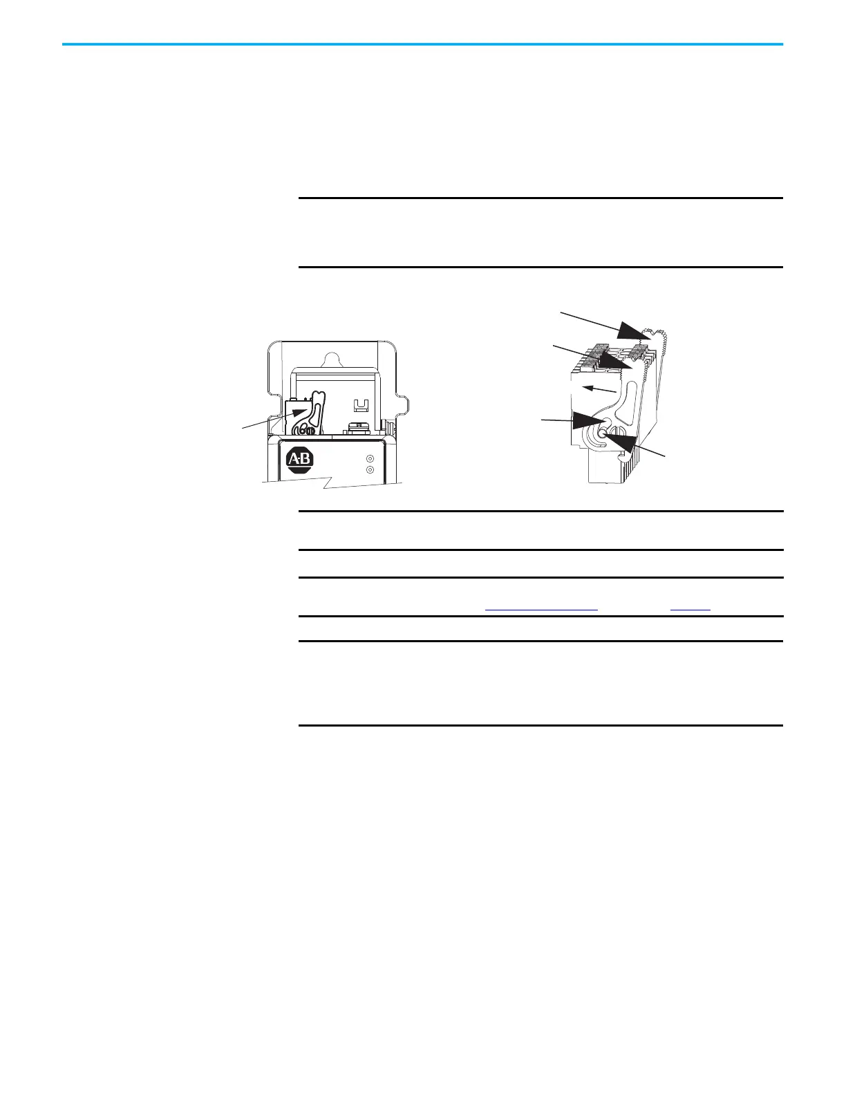
Install 2198-xxxx-ERS4 and 2198-xxxx-ERS3 (series B) Safety Connector Plugs
The safety connector plugs have two locking leavers that you push in a
clockwise direction as you insert the plugs into the drive connector. This is the
locked position. Rotate the leavers counter-clockwise to the open position to
release the connector plugs. This applies to 2198-xxxx-ERS4 and
2198-xxxx-ERS3 (series B) single-axis and dual-axis inverters.
Figure 140 - Insert the 2198-xxxx-ERS4 and 2198-xxxx-ERS3 (series B) Safety Connector Plugs
IMPORTANT
Push the locking leavers clockwise into the locked position as you
insert the STO connector plugs. Failure to do this can result in the
connector plugs pulling out of the drive connector during normal
operation.
Locking Leavers in
Locked Position
Locked Position
(rotated clockwise)
Kinetix 5700 Inverter Drive
(2198-xxxx-ERS4 inverter is shown)
Open Position
(rotated counter-clockwise)
Push to Lock
Push to Lock
Push to Unlock
Safety (STO) Connector Plug
IMPORTANT
The National Electrical Code and local electrical codes take precedence
over the values and methods provided.
IMPORTANT
To improve system performance, run wires and cables in the wireways
as established in Establish Noise Zones beginning on page 67.
IMPORTANT
Pins ST0-1 and ST0-5 (SB+ and SB-) are used to disable the safe torque-
off function. When wiring to the STO connector, use an external 24V
supply for the external safety device that triggers the safe torque-off
request. To avoid jeopardizing system performance, do not use pin
ST0-1 as a power supply for the external safety device.

 Loading...


