Rockwell Automation Publication 2198-UM002L-EN-P - October 2021 63
Chapter 2 Plan the Kinetix 5700 Drive System Installation
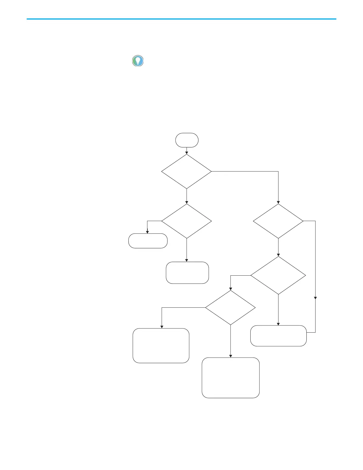
In this flowchart, a 2198-Pxxx DC-bus power supply or 2198-RPxxx
regenerative bus supply supplies DC-bus power to a multi-cluster drive
system. System variables that you need to know include the following:
• The type of AC to DC converter used
• The input-power ground configuration
• The external DC-bus current
• The total motor-cable length of the power supply cluster
Figure 34 - Multi-cluster Drive System
The ‘power supply’ cluster includes the 2198-Pxxx DC-bus power supply
or 2198-RPxxx regenerative bus supply. Extended clusters are part of the
same DC-bus group and connected to the power supply cluster via stud
terminals that are available on accessory modules.
<104 A
<400 m
(1312 ft)
≥400 m
(1312 ft)
<104 A
Each Cluster:
• Capacitor Module
•Extension Module
What type of AC to DC
converter is used?
Start
Is this an impedance
grounded system?
What is the total
motor cable length of
the power supply
cluster?
What is the
external DC-bus
current?
DC-bus Power
Supply
Regenerative Bus Supply
Yes
No
Each Cluster:
Capacitor Module
Each Cluster:
• Capacitor Module
• DC-bus Conditioner Module
Power Supply Cluster:
• Capacitor Module
All Extended Clusters:
• Capacitor Module
• DC-bus Conditioner Module
Power Supply Cluster:
• Capacitor Module
•Extension Module
All Extended Clusters:
• Capacitor Module
• DC-bus Conditioner Module
What is the
external DC-bus
current?
≥104 A
up to 208 A, max
≥104 A
up to 208 A, max

 Loading...


