A.13
Date Code 20080213 Instruction Manual SEL-351A Relay
Firmware and Manual Versions
Instruction Manual
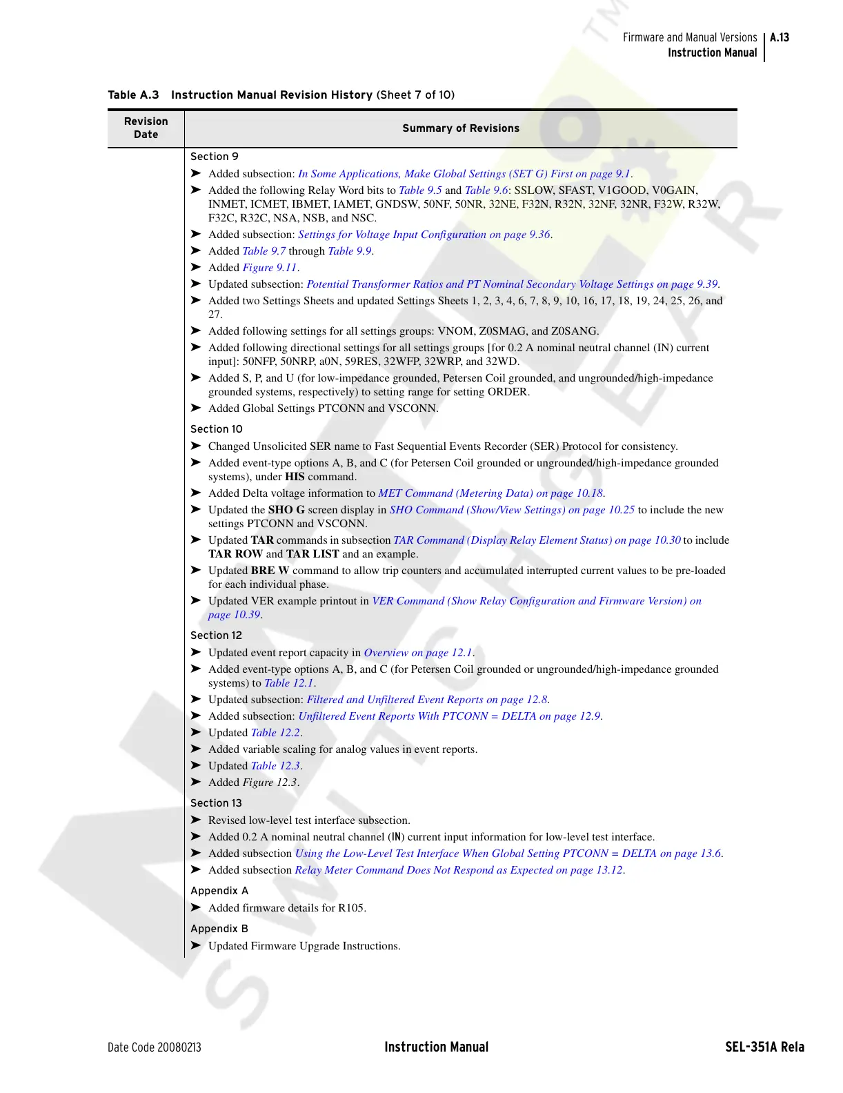
Section 9
➤ Added subsection: In Some Applications, Make Global Settings (SET G) First on page 9.1.
➤ Added the following Relay Word bits to Tab le 9 .5 and Ta ble 9 .6 : SSLOW, SFAST, V1GOOD, V0GAIN,
INMET, ICMET, IBMET, IAMET, GNDSW, 50NF, 50NR, 32NE, F32N, R32N, 32NF, 32NR, F32W, R32W,
F32C, R32C, NSA, NSB, and NSC.
➤ Added subsection: Settings for Voltage Input Configuration on page 9.36.
➤ Added Tab le 9.7 through Tab le 9 .9.
➤ Added Figure 9.11.
➤ Updated subsection: Potential Transformer Ratios and PT Nominal Secondary Voltage Settings on page 9.39.
➤ Added two Settings Sheets and updated Settings Sheets 1, 2, 3, 4, 6, 7, 8, 9, 10, 16, 17, 18, 19, 24, 25, 26, and
27.
➤ Added following settings for all settings groups: VNOM, Z0SMAG, and Z0SANG.
➤ Added following directional settings for all settings groups [for 0.2 A nominal neutral channel (IN) current
input]: 50NFP, 50NRP, a0N, 59RES, 32WFP, 32WRP, and 32WD.
➤ Added S, P, and U (for low-impedance grounded, Petersen Coil grounded, and ungrounded/high-impedance
grounded systems, respectively) to setting range for setting ORDER.
➤ Added Global Settings PTCONN and VSCONN.
Section 10
➤ Changed Unsolicited SER name to Fast Sequential Events Recorder (SER) Protocol for consistency.
➤ Added event-type options A, B, and C (for Petersen Coil grounded or ungrounded/high-impedance grounded
systems), under HIS command.
➤ Added Delta voltage information to MET Command (Metering Data) on page 10.18.
➤ Updated the SHO G screen display in SHO Command (Show/View Settings) on page 10.25 to include the new
settings PTCONN and VSCONN.
➤ Updated TAR commands in subsection TAR Command (Display Relay Element Status) on page 10.30 to include
TA R ROW and TAR LIST and an example.
➤ Updated BRE W command to allow trip counters and accumulated interrupted current values to be pre-loaded
for each individual phase.
➤ Updated VER example printout in VER Command (Show Relay Configuration and Firmware Version) on
page 10.39.
Section 12
➤ Updated event report capacity in Overview on page 12.1.
➤ Added event-type options A, B, and C (for Petersen Coil grounded or ungrounded/high-impedance grounded
systems) to Table 12.1.
➤ Updated subsection: Filtered and Unfiltered Event Reports on page 12.8.
➤ Added subsection: Unfiltered Event Reports With PTCONN = DELTA on page 12.9.
➤ Updated Table 12.2.
➤ Added variable scaling for analog values in event reports.
➤ Updated Table 12.3.
➤ Added Figure 12.3.
Section 13
➤ Revised low-level test interface subsection.
➤ Added 0.2 A nominal neutral channel (IN) current input information for low-level test interface.
➤ Added subsection Using the Low-Level Test Interface When Global Setting PTCONN = DELTA on page 13.6.
➤ Added subsection Relay Meter Command Does Not Respond as Expected on page 13.12.
Appendix A
➤ Added firmware details for R105.
Appendix B
➤ Updated Firmware Upgrade Instructions.
Table A.3 Instruction Manual Revision History (Sheet 7 of 10)
Revision
Date
Summary of Revisions
Courtesy of NationalSwitchgear.com
 Loading...