Section 06 ENGINE MANAGEMENT (RFI)
Subsection 03 (COMPONENT ADJUSTMENT, INSPECTION AND REPLACEMENT)
smr2005-056-008
CAUTION: If not using the ECM adapter, probe
on top of terminal only. Do not try to probe in-
side terminal or to use a paper clip to probe in-
side terminal, it will damage the square-shaped
terminal and this could lead to improper func-
tion of the engine management system.
A32CCPA
PROBE ONLY TOP OF TERMINAL
Use this diagram to locate the terminal numbers
on the ECM connector A of the wiring harness
when performing tests.
R1503motr176A
1
13
28
41
29
14
TERMINAL IDENTIFICATION OF ECM CONNECTOR A
(WIRING HARNESS SIDE)
CAUTION: Do not disconnect the ECM connec-
tors needlessly. They are not designed to be
disconnected/reconnected repeatedly.
NOTE: For more details on ECM connectors ser-
vicing, refer to ELECTRICAL CONNECTORS AND
WIRING DIAGRAMS section.
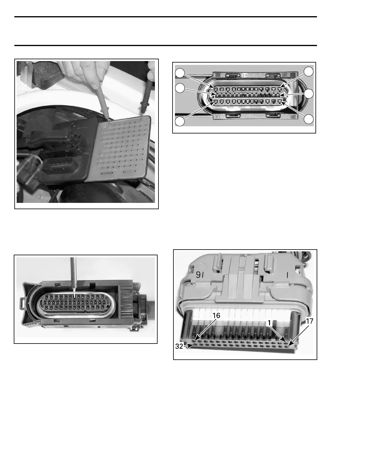
VCM Connectors
32-Pin Connector
The connector terminals are identified as follows:
Starting from the right on the top row, terminals 1
to 16. On the bottom row, terminals 17 to 32.
smr2005-056-009_a
7-Pin Connector no. 6 and 7
The terminals of this connector are identified by
letters.
128 smr2005-056