Section 07 ELECTRICAL SYSTEM
Subsection 03 (STARTING SYSTEM)
smr2005-058-003_b
1. Main fuse
Fuse F4: 10A, Ignition coil and starter solenoid
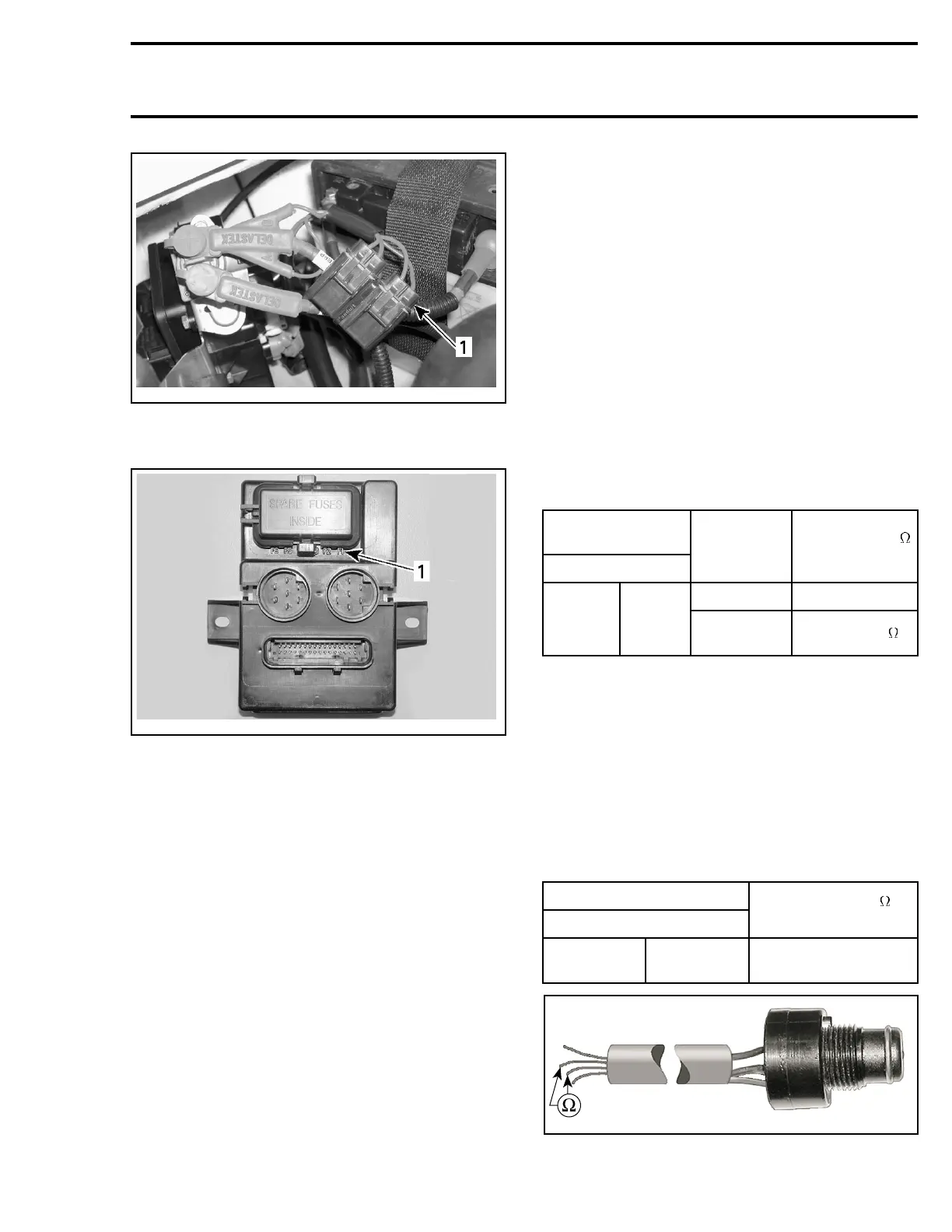
smr2005-059-007_a
1. Fuse location and identification
Power Supply Cut-off Relay
717 Engine
The relay is located in the cover of the electrical
box.
First ensure the DESS switch works properly (see
testing procedure further).
Test the signal wire (BLACK/PURPLE) to the pow-
er supply cut-off relay as follows:
Disconnect the connector on electrical box.
Using a voltmeter, perform the following tests:
Connect test probes to the small RED wire on
the starter solenoid and on the RED/PURPLE wire
from the cut-off relay. Reading should be 0 V. Oth-
erwise, replace the cut-off relay.
Keeping the test probes on the same wires, con-
nect a jumper wire between the BLACK/PURPLE
wire from the cut-off relay to the battery ground.
Measure voltage. Reading should be 12 V. Oth-
erwise, check wiring and if it is good, replace the
cut-off relay.
If there is no current supply to the electrical com-
ponents while the DESS switch and the cut-off
relay test good, check the wiring harness and
connections. If everything test good, the MPEM
couldbesuspected.
Engine Start/Stop Switch
Disconnect start/stop switch connector. Measure
resistance between switch wires as per table.
NOTE: On 3D models, check both switches one
at a time.
SWITCH
CONNECTOR
WIRE
SWITCH
POSITION
RESISTANCE
@20°C(68°F)
Released
Open circuit
YELLOW/
RED
PURPLE
Depressed
and held
Closeto0
If any test fails, replace switch.
DESS Switch
Perform the following continuity tests using an
ohmmeter:
Disconnect switch wires.
Safety Lanyard Removed
Connect test probes to switch as per tables and
measure resistance.
SWITCH CONNECTOR
WIRE
RESISTANCE
@20°C(68°F)
BLACK
BLACK/
YELLOW
open circuit
smr2005-057-007_a
smr2005-059 187