Section07ELECTRICALSYSTEM
Subsection 03 (STARTING SYSTEM)
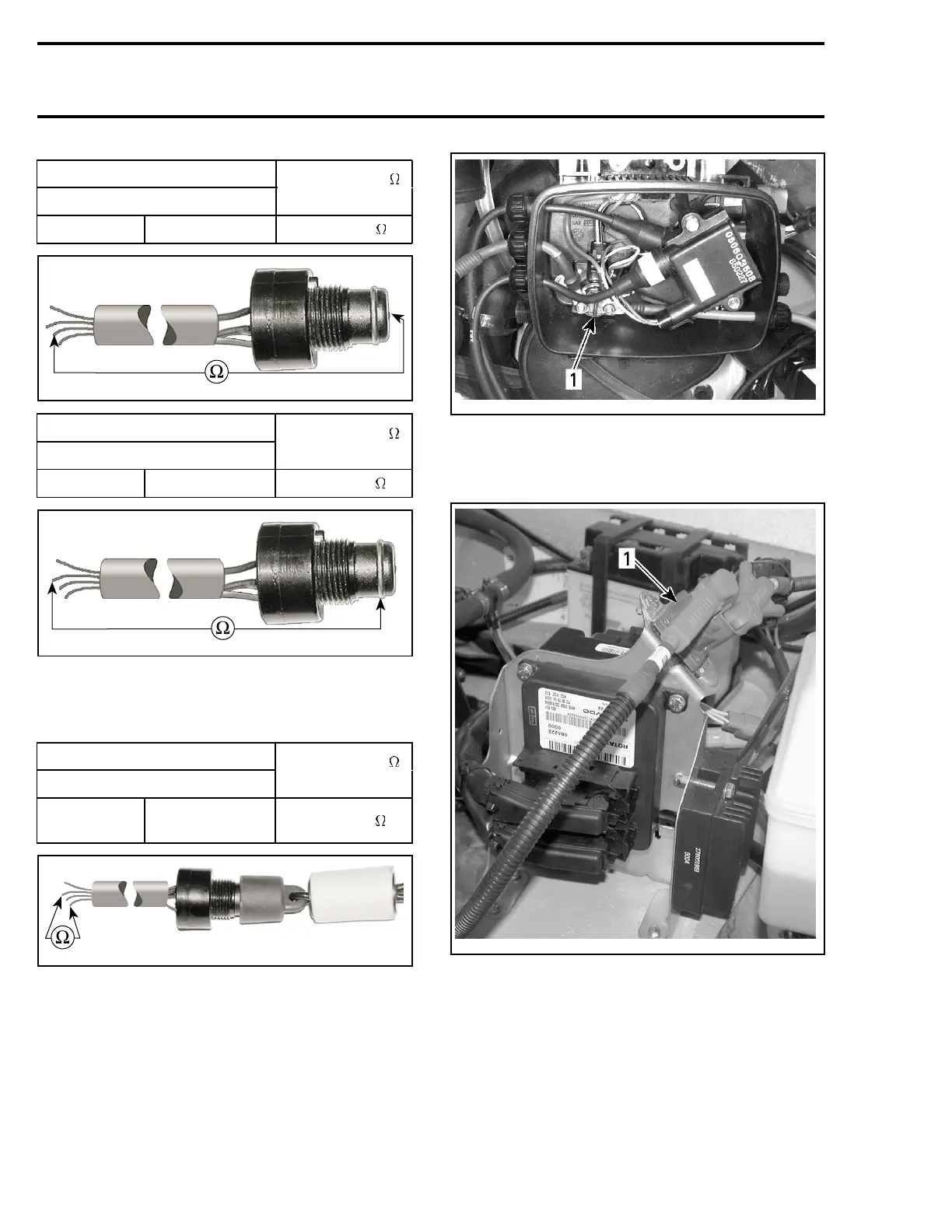
SWITCH CONNECTOR
WIRE
RESISTANCE
@20°C(68°F)
WHITE/GRAY
switch terminal close to 0
smr2005-057-007_b
SWITCH CONNECTOR
WIRE
RESISTANCE
@20°C(68°F)
BLACK switch ring close to 0
smr2005-057-007_c
Safety Lanyard on Switch
Connect test probes to switch as per table and
measure resistance.
SWITCH CONNECTOR
WIRE
RESISTANCE
@20°C(68°F)
BLACK
BLACK/
YELLOW
close to 0
smr2005-057-010_a
If any resistance test fails, replace DESS switch.
Solenoid
717 Engine
The Solenoid is located inside the rear electrical
box.
smr2005-059-002_a
1. Solenoid
787 RFI Engine
Solenoid is located above ECM/VCM.
smr2005-058-002_b
1. Solenoid
Inspect connections and clean as necessary.
All Engines
Static Test: Continuity
With a multimeter, check prim
ary winding resis-
tance as follows.
188 smr2005-059